Thursday, September 23, 2010

DCTL vs Full-Size Vertical

I was asked a very justified question, how well the DCTL-antenna would actually work. To test this, I was running the spectrumlab-grabber on a full-size vertical for 30m. The vertical is made from flimsy speaker twin-lead, cut to a length of 7.2m; both leads parallel. The vertical got two radials, made from the same stuff, cut to the same length. A telescopic fishing-rod keeps the vertical vertical.

On the left side of the following spectrum, I can see a spectrum taken with the vertical, the spectrum on the right hand side is taken using the DCTL.


It is somewhat obvious that the vertical delivers more signal. In terms of signal to noise ration, the DCTL is in a 3dB lead. Well, the slightly better S/N-R is not really visible, since I run WSPR parallel to SpectrumLab, it was actually measured. You may however get the impression that the FSK signal on 10140060Hz is somewhat clearer when the DCTL was use.

I have to add that the DCTL is placed next to a wall, the distance I would estimate as 20cm. With the DCTL not being proximate to other objects, and may somewhat higher, signals would probably be much better. Something still to be investigated.

The Subharmonic (Frequency Doubling) Mixer

This is one of my favorites, the subharmonic mixer. It sound complicated, it may be, but, to build it is not.
How, let's have a look on the options of mixing.

Mixing of a signal with a local oscillator (LO) can be done in two ways, either enable the bypass of a signal in the "rhythm" of the LO or shorten the signal in the "rhythm" of the LO. Usually this is done by a single "non linear element", e.g. diode. In the positive 0-180 degrees of phase, the diode is open, letting through the signal, in the negative 180-360 degrees of phase, the diode is closed, blocking the signal. Alternatively, shorting the signal to ground using the diode would provide the same results, a sum and a difference of the two frequencies.
So far so good...

But where's the doubling?!
Well, here it comes. Assume that two anti-parallel diodes are used as a mixer. Given that the LO is adjusted to the correct level, the first of the two diodes is open for one 1/4 of the period (90 degrees) on e.g. 50% of the positive half-period of the LO and the second of the two diodes is open for another 1/4 of the period (90 degrees) on e.g. 50% of the negative half-period of the LO. This would correspond to the mixer's diodes being open during the phase angles 45-135 degrees and 225-315 degrees. Compared to the 0-180 degrees a single diode would be open, the frequency is effectively doubled.

There are some advantages to this approach. In a direct-conversion receiver, the LO is far of the receiver's front-end, the preamp would therefore be unaffected. Also, a lower frequency oscillator is less critical in design. Any variation of the LO will have double impact on the operating frequency... this has pros and cons, e.g. VXO.

I like using sub-harmonic mixers, try 'em out for yourself!

Frequency dividers and their use

Some more off the howto-stuff, I lately started. Sometimes I was mentioning that a frequency should be divided... now, that is strange! So far we had it about multiplication of frequencies by some sort of factors, and now division?!
Yes, rather simple, yes really!

In the digital world, some thing are out there called counters. There are a couple of different counters available. The most primitive of all is the Flip-Flop, which is counting to 2.
Now, how does a Flip-Flop help to divide a frequency? Very simple, have your oscillator's signal on the clock input... .... ah well, it has been written before, check this out.
So, here you got it, cascading Flip-Flops will result in a division by 2^x, as cascading doublers did for multiplication. The cascade of Flip-Flops is known as Ripple-counter.

You may ask yourself, if division by odd numbers would be easily possible, as easily as multiplication was. The answer is NO. One can use hexadecimal or decade counters to divide a frequency, just as it is done with a ripple-counter, however, there is a disadvantage. A ripple counter ensures a 50% duty cycle, i.e. HIGH for half a period and LOW for the other half, which is symmetrical and can be smoothed to a sine-ish waveform by a low-pass filter. Any other counter-divider, however, will result is a duty cycle being off. So, what you really want to do is, ensure that your final division is EVEN and use a Flip-Flop as the last stage. Example: we would like to divide a frequency by 10. We would first use a decade counter, counting to 5. The resulting pulse would be sent to a Flip-Flop, so that the total amount of division would be 10. Always try to have your duty cycle as close as possible to 50%. Assume you need a division by 21. Use a decade counter to divide by 7 and cascade it with a counter to 3. This will give a 33% duty cycle, still relatively symmetrical, compared to a 14% duty cycle in reverse order....

The VXO

Oscillators using crystals, aka XO, are supposed to be a reliable source of signal having a stable frequency. OK, compared to VFOs (Variable Frequency Oscillators), using inductors and capacitors, that is safe to say, however, there are some remarkably stable VFO designs out there...

The whole game of combining crystal frequencies, at least for A1A or F1A purposes is, to avoid the potential drift a regular VFO would possibly suffer from. Well, amateur radio, as we all know, is not a channelized game however. So, what are those crystals and combinations of xtal-qrg good for when it comes down to usability?

Well, first of all, there are some frequencies of major interested, such as the QRP callings QRGs. A rig covering a single frequency could still be very useful, depending on the frequency and its use. Just remember the good old times, everyone was using a color burst crystal (3.579MHz) and had a great share of fun.

A crystal oscillator can provide so much more than just a single frequency. And this is why:
a crystal is functioning as some sort of L-C (inductor-capacitor) resonant circuit (check out the internet for more info). Such circuits can be influenced by additional reactance, e.g. a capacitor and/or inductor in series, which will bend the resonant frequency either up or down.
Using the right amount of (variable) inductance and/or (variable) capacitance, a crystal's resonance can be pulled by a certain percentage, which can be quite a bit depending on the frequency.
This frequency pull can further be enhanced by using two or more crystals in parallel. Now we are talking "super VXO" (please check the internet, there is some very good documentation available from Japan).

What's the benefit? Assume we are going back to the example for the 40m band, used in the xtal-combi-post. Assume we pull the 8.867MHz oscillator by +/- 5kHz (which is no problem on that frequency at all), the resulting mix with a 1.843MHz frequency would allow for a range of 7.019 to 7.029Mhz, representing a very useful portion of the 40m CW range. With a super-VXO, this range could be from approx. 7.000 to 7.040Mhz.
This is what crystal combinations are all about. A stable VXO converting into a "cheap" I.F., and we got us a
cheap receiver having a crystal CW-filter.

BTW, this is what this entry was all about.

Wednesday, September 22, 2010

Frequency multipliers and their use

Sometimes, one may want to multiply a frequency by factors other than two (doubling, see earlier post).

Here is an example why you actually may want to do this. What about a crystal controlled 30m band (10.100...10.150MHz) signal generator to generate a frequency of 10.118MHz using cheaply available xtals?
  • 3 * 7.3729 - 12.000  =  22.1187 - 12.000 = 10.1187
Hmmm, now we have to triple one of the frequencies... Yep, no problem. The trick is to use generate a picket fence of harmonics and filter out the one we want.
The spectrum of a square wave signal consists of odd harmonics. Hence odd multiplications are available by simply "clipping" the original signal, in other words, convert it into a square wave, and filter out the harmonic of interest.
In the digital age, one may think of using a digital gate, e.g. XOR or NOT (inverter), to generate a nice frequency fence in the first place.

Back to our example, in order to create our signal, we would build a square-wave generator using a 7.3729MHz crystal, filter out the 22.1187Mhz contribution and mix it with 12.000MHz.

Closing with an academic one: One may want to multiply a signal by 6. This could be done by filtering the 3rd harmonic and double it by means of a diode doubler...

Frequency doublers and their use

Occasionally, one might have seen that I mentioned a frequency had to be doubled. Why is that?!

Assume we want to generate a signal in the 12m band (24.890...24.990MHz). We could aim for a frequency of 24.915Mhz. This frequency could easily be synthesized by means of cheap computer crystals as follows:
  • 24.915 = 20.000 + 4.915 = 2 * 10.000 + 4.915
There would be two options:
use a 20.000MHz crystal in an oscillator and mix this signal with the 4.915MHz signal
or

use a 10.000MHz crystal in an oscillator, frequency double the generated 10.000MHz, resulting in 20.000MHz and mix that with the 4.915MHz.

There are a couple of ways to double the frequency of a radio frequency signal.
One of the most simple ways is using just simple (fast switching) diodes in a sort of rectifier circuit. A rectifier folds the negative valley of an AC signal to positive. We obtained two positive humps per cycle, meaning that the resulting AC signal has twice the frequency of the original signal. Yes, it as easy as that.

There are other methods, e.g. using XOR digital gates and a phase shifter, please check the internet for other solutions.

As a closing remark, frequency doubler can be cascaded. With the occasional amplification, one can easily build multipliers for factors 2^x, e.g. 4=2*2, 8=2*2*2, 16=2*2*2*2....

Full Duplex QRSS TRX

I was dreaming about this for a while (see earlier entry), get some inter-activity into QRSS. What about having full-duplex QSOs in a single band? I figure, given the narrow bandwith, this would just be possible.
All it needs is in-band crystals for filtering.
We have got a couple of in-band crystals available, here are some options:
  • 3.500 & 3.579
  • 7.000 & 7.159
  • 14.000 & 14.318
Those pairs have a particular advantage, they are harmonics. Which allows for some neat designs. One could image multi-band rigs with those, e.g. direct-conversion on 80 and subharmonic (doubled) on 40, or the same with 40 and 20, or, have a direct-conversion tri-band rig with oscillators running on 20 while the frequencies could be divided by FlipFlops.

A possible DX-rig could be 20 and 40, while a NVIS-rig could be 40 and 80.

For single band TRXs there would be more options, such as
  • 3.579 & 3.868
  • 28.188 & 28.322
or any other widely available pair (check out the shops run by N4ESS or VK1AA).

To the design of such a system, the following could be said, one would either work with changeable modules, or build two full transceivers.
The latter option could be a simple a building two Rock-Mites. Those little transceivers could easily be modified for FSK. Another solution could be the PSK-Warbler design; unfortunately, the kit has been retired by now.
Modular could be somewhat like this: modules for the oscillators and filters and a common mother-board carrying the mixers and the rest. The easiest way would probably be to build one module only such that it can be mounted in two different orientations. That would just required the pins of the module being symmetrically arranged. In that way, one could easily change from LOW-TXing to HIGH-TXing by just reorienting the one module.
Another idea would be to build two full receivers and one switchable transmitter. With would allow to constantly monitor both frequencies, i.e. with individual spectra for left/right audio channels under Spectrumlab.

The remaining challenge would be to decide for the aerials. I figure reception would be done best using magnetic loops or other very narrow-band contraptions, while transmission is probably done best with a vertical of a dipole.

Anyone prepared to join the fun and build something alike?

Numbers and Combinations thereof (experts, please ignore this entry!)

OK, slowly but surely, I got behind the mystery that is perceived in the numbers I occasionally publish.
The mystery goes as follows:
Use the cheapest available material (i.e. electronic components) in order to be active in the ranges in which radio amateurs are allowed to operate. That's it! No secret message in here!
Example:
We want to operate (transmit or receive) in the 40m band CW (Morse code or telegraphy) section, we can easily use a superhet (supersonic heterodyne) design mixing two different frequencies such as 8.867Mhz and 1.843MHz resulting in two mixing products, the sum which results in 10.71MHz and the difference resulting in 7.024MHz. Using a low pass filter, one will remove the sum of the two frequencies and end up with the difference, which is at a very convenient place on the telegraphy portion of the 40m amateur radio band.
The trick, or secret if you insist, is to use two standard crystals, which are cheap to obtain anywhere, and mix those up.... that's all.... In a superhet receiver design, one of those frequencies can be used as an intermediate frequency filter, using simple ladder filters, made from those cheaply available standard crystals.
Please, go through all the numbers I published so far and tell me if there is anything wrong with those... Some combinations are to be found on this blog, some here and even more here.
As I said, experts, please ignore this....

Tuesday, September 14, 2010

Hybrid SDR Dual Grabber

 Testing new aerials is a nice thing, however, comparison to a known antenna would be a nice thing to do.
Actually, this has been done before, by Claudio i2NDT (check it out!).

So, what's the big fuzz about another approach? Well, testing with transmitters would not allow for testing active antennae, obviously. So, what will it be, 2 receivers of the same make? Well, maybe. Tolerances could still play tricks and mess up the measurements.

If you think of it, the solution is as obvious as it is simple... almost a miracle that nobody was writing about it before: use an I/Q-SDR direct conversion receiver with some slight modifications.
Such a receiver actually consists of two identical receiver sharing a local oscillator. The 90 degrees phase shift
Even the cheapest of I/Q-SDR receivers aims for the I and the Q channels being matched as good as possible. Usually, low tolerance parts are used all over.

As modification I would consider the following (once again one of my lists):
  1. add a switch to toggle between the usual 3dB splitter and two individual (crystal) filtered front ends
  2. configure spectrum-lab to show left and write audio channels in individual waterfalls
If it wasn't for the 90 degrees phase shift, one could consider some right-left channel correlations. So, one may consider to remove or bridge the phase shifting circuitry. However, having the I/Q-phase shift allows for full bandwidth SDR action, which in itself can be used to check the balance between the two receivers.

Wire Hairpin Monopole?

Stumbled across it, you guessed it, on the internet (interestingly enough, Juan EA5XQ (*) also tried out the DCTL too). A mono-band simple to build aerial, you guessed it again, just to tempting for me, so I built one for 30m to test it on the grabber.

Reaching about in my stock of raw material, a roll of flimsy speaker twin-lead (non-HiFi, just the cheapest stuff). In order for me to roughly know what to do, the dimensions of the cable were roughly measure and hacked into my favorite antenna simulation program (MMANA). The software optimized the monopole's length to 7.6m.

This method of making a monoband aerial was performed in the middle of the night
  1. cut 7.6m of twin-lead speaker cable
  2. leads shorted at a first end of the cable
  3. leads split at a second end of the cable, opposite the first end of the cable
  4. done
The whole contraption is now connected to the "Ant A" port of the grabber's FRT-7700.

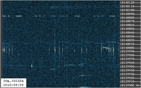
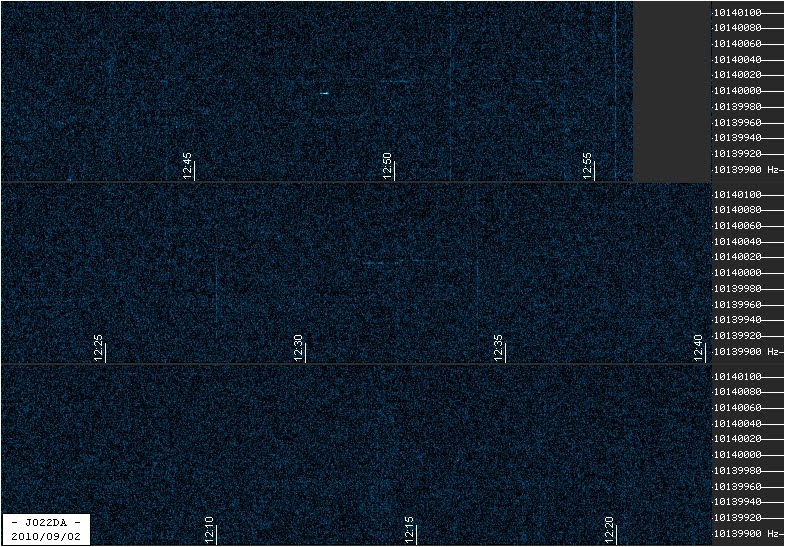
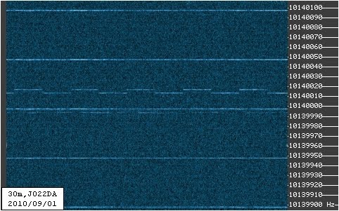
The hairpin monopole clearly provides much more signal than the DCTL (on the "Ant B" port) and much more noise too. So much more noise that signals are actually drowned in it... Have a look, 2028z I switched back to the DCTL. Check the faint traces at 1958z vs 2030z...

Hairpin vs DCTL

Compared to the DCTL, the hairpin monopole is a much easier build, even though the DCTL is not the toughest either.
I decided which will be my grabber antenna for the time being. Draw your own conclusions, either of the aerials has got pros and cons....

Next: test the TXing capabilities of the hairpin monopole.

(*) Interesting twist of history, I built my first DCTL in 1997 inspired by some list postings. Only since I re-employed the aerial for grabbing, I researched the internet again for it, in the hope of some more experiences. Juan's webpage made me aware of the monopole, so I tried it. Funny bit, I came to the opposite conclusion, at least for grabbing on 30m, the DCTL works much better. I also had some QSOs on 30m and 40m, using the DCTL. With the help of my 1997 DCTL the 40m mod of the warbler received the other side of the globe and my few signals were received from many stations.

UPDATE (18th September)
Had the grabber running for one night and one day running on the hairpin. The success was very limited. I tried matching w/ simple poly-varicons, well, I could tune it to 1.2:1 @ 50Ohm... on 20m... yes, twenty.... hmmm! From here on, the DCTL seems to be the mroe simple solution, some twin-lead and a balun.
There will be one more test, having the hairpin installed vertically.

Sunday, September 5, 2010

QRSS Averaging - Redundancy

With the help of Alessandro IW3SGT, I was able to collect some interesting data. Alessandro set his transmission so that his ident is sent out twice in a 10min period. Timing was perfect!
Towards the end of the session, strong fading dominated the game, and this is what this entry is about.

The last 30min of the opening look exactly like this

1800z - 1810z
1810z - 1820z
1820z - 1830z

The above spectra never show "SGT" completed. Have a look at the average of those spectra:


Here we go, thanks to the ident being TXed twice in the course of 10min, it is easy to figure out the ident from the averaged spectra.

BTW, adding the frame from just before the above mentioned 30min, result is really obvious...

1750z - 1800z
40m average
I am not sure, I remember to have observed a QSB frequency having a period of about 10min, that was on 600m, trying to decode G3ZJO's WSPR. Maybe a 10min averaging is not such a good idea after all, and 5min should be chosen.

Saturday, September 4, 2010

QRSS Averaging vs Plasma TV - 2nd Test

Short update on averaging fighting a plasma TV.

I selected the best and the worst of the 10 frames used for averaging. It seems that every plasma TV has got its own finger-print...

Let's have a look:

best frame

worst frame

average of 10 frames
... using the (old) dark frame
... dark frame and cut "low" pixels
This shows, as long as the local noise is regular enough, one can either simply ignore it, or fight it with simple measures. I think, I could do better on the dark frame story, however, I still lack pure TV signal to create my "plasma frame".


UPDATE
6 frames stacked (no dark frame), positive QRSS identification of "SGT" despite the plasma TV... more to learn. I should make my dark frame soon.
positive identification of SGT

Friday, September 3, 2010

Magic super-VXO Frequency?

Years ago, I ebayed a Heathkit HW-8 direct conversion CW-transceiver. It was not in the best shape, but it did not cost the world either. Now, for good measures, finally I want to put some life in it again. So, lets look at the schematics first...
Ahh, mhhhh, aha..... four bands, four crystals and a 250kHz wide VFO.
Lets have a look at the combination for 80m:
The converter-crystal is mentioned to be 12.395MHz. That would determine the VFO oscillating at 8.895MHz at its maximum frequency.

Hmm, 8.645MHz to 8.895MHz, that rings a bell! Yes, you guessed it, there is a widely available standard crystal at 8.86724MHz, resulting a very interesting operating frequency at about 3.528MHz... Interesting, a super-VXO at 8.867MHz, will get us 28kHz off from the lower edges of the four bands.

Now lets see how well a 8.867 super-VXO will do with other standard crystals...
  • 8.867 - 9.000 = (-) 0.133
  • 8.867 - 7.000 = 1.867
  • 8.867 - 12.406 = (-) 3.539
  • 8.867 - 1.843 = 7.024
  • 8.867 + 5.185 = 14.052
  • 8.867 + 9.216 = 18.083
 You're missing 30m? OK, here's your 30m, it's a tricky one however, in particular for filtering!
  • 8.867 + (5.000/4) = 8.867 + 1.25 = 10.117
 Or with a not so common 38.0MHz oscillator:
  • 8.867 - (38.000/2) = 8.867 - 19.000 = (-) 10.133

I leave it to the reader to find more, in particular for the bands 15m and higher...

Thursday, September 2, 2010

QRSS Averaging vs Plasma TV

Well, what about those, would you think that any reasonable signal identification can be derived from this? "Ja hoor!"


Raw Data

Feel free to download the images and try for yourself!


Averaged Spectrum

And we can identify Paolo once again ;-)


Dark Frame Technique vs Plasma TV

A plasma TV creates some more or less static lines, like hot pixels in a long exposure CCD camera. The dark frame technique subtracts the "ideal" hot pixel map, or TV lines, in our case. A dark frame is created the same way as the averaged spectum. In the case of a CCD camera, one simply puts the lid on the objective lens. For TV, life is more complicated. To create a dark frame, I selected spectra were the TV lines were essentially the only signals present. Maybe, in a second step, one may want to try to capture spectra of the particular noise source with an insensitive antenna close by...
That would be my dark frame for tonight (5 selected spectra averaged):


With dark fram "opacity" set to 30%, that's what the little averaging program comes up with:


DF opacity set to 100%, pixel values of less than 160 are set to 0.


Dark Frame Technique vs OTHR

Yep, this technique is suitable for getting rid of radar stuff too. To me, it seems more to help aesthetics than anything else... but... you never know.
Last night, nice radar spectra were recorded. A couple of those resulted in the following radar "dark frame":


Earlier today, that was recorded... (averaged)


Averaged using the dark frame:


Conclusion

Those are my first steps using my experience in imaging gather in long-exposure webcam deep sky photography. I am in a very early stage using said techniques in QRSS imaging. My impression is,
imaging techniques used in astrophotography can help QRSS. Those techniques can even help fighting local QRM. A lot more learning is required... I remember my learning curve in astro-stuff... my first astro-images totally sucked!

Daytime Averaging

Unfortunately, the night did not really reveal any good condx. However, during daytime, very poor condx allowed to see some Southern European signals.

During the time span in question, the regular grabber took the following spectra


In the time between 10:30 and 13:00 UTC, 15 10min spectra were taken. Successive 5 of those spectra were average into 3 intermediate results, which were averaged again. Remember the demo-version of the stacking software allows for max. 10 images to be treated.


Averaging Result


Metallic Effect (irfanview)


Paolo's FSK signal nicely spreads over the full 10min span. Due to fading, the signal never made it into JO22 for any continuous 10min, as the 15 "frames" show.

The SNR could be further improved by selecting the best spectra, i.e. with at least some signal. I went for the "blind" method (using all frames) an automatic grabber would perform.

If interested in the raw spectra (frames), drop a comment, I will make a zip-file available for download.

QRSS Image Averaging

First test on 10min QRSS spectra averaging using http://tawbaware.com/imgstack.htm
Thanks to NH7SR, it seem somewhat obvious how to record timed spectra. With good stability and timing assume, image registration seems not to be required. Hence, simple stacking or averaging would be a promising start. Here's some first stuff, not refined yet... a somewhat early pre-alpha stage.


Raw Data

The following 6 images are raw spectra, as recorded and used for the averaging.

Raw
Raw
Raw

Raw

Raw

Raw


Averaging Result

Average


Conclusion

The settings are pretty much same used for the online grabber. For an averaging grabber, more noise, i.e. contrast & brightness, could be tolerated. Data acquisition with more aggressive settings is presently ongoing.
I believe, the first hour, compressed into 10 minutes show a promising start and some potential when the learning curve is surpassed.


Update

Some more spectra are in, as promised, more aggressively set. This is what those look like.

Raw
Raw
Raw
Raw
Average