Sunday, January 31, 2010

Warblers on WSRP II

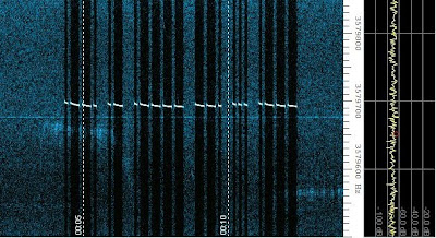
There is a reason for me t have ordered two kits. The 30m version I did explain in an earlier post.
The Warbler can be equally easy (if not even easier) modified into a 40m WSPR transceiver.

That what needs to be done:

  • use 7.040MHz crystals for the filters
  • use a 7.038MHz crystal for the oscillator
  • pull the oscillator frequency to 7.0386Mhz
  • adapt the PA and low pass filter to 40m
DONE!

One could consider using the sound cards audio signal to key the transmitter, there are simple solutions out there. See also Dave's PSK20, which is audio keyed. Documentation on Dave's webpage.

QRSS RM80 final verdict (QRT)

Here's what you wanna do when going for a Rock-Mite-80-QRSS-mept/grabber.
  1. get a Rock-Mite 80 kit from Dave
  2. get two 3.579545MHz crystals
  3. get one 4.7pF and one 22pF capacitor
  4. build the kit, leaving out C8 (beep beep)
  5. for C12, use 4,7pF in place of 47pF (reduces chirp)
  6. for C2, use 22pF in place of 33pF (lifts filter response)
  7. get a 8-pin PIC (to replace U3) and program it as wanted

The reduced coupling from the oscillator to the (keyed) buffer results in lower output power. 4.7pF to me seems the working compromise. I tried all of the following values (in order of the experimentation timeline): 47pF (original - severe chirp, PA becomes hot), 27pF (still intolerable chirp, PA warms slightly up), 2.2pF (no chirp at all, nearly no power), 18pF (chirp), 10pF (chirp), 7.5pF (still too much chirp) and finally 4.7pF.

Optional, a 10V Zener diode could be dropped into D5's empty place. This will lower the "upper" qrg by about 200Hz, further reducing chirp.

For the mode, I would advice A1A with QSK, for timing, QRSS6 will do just fine. 

Programming: With no further hardware modification, an 8pin PIC, such as the 12F629 can be used.
GPIO4 low will provide the varicap diode with 12V, resulting in the higher frequency, which is used for TX.
GPIO5 high will key the buffer and the PA.
I found that it is sufficient to low GPIO4 just before keying the transmitter. Returning GPIO4 to high directly after transmission allows for full QSK. No additional chirp in the TX signal.
To also receive, e.g. as a grabber, my program receives for 10min before TXing the message again.

I did all that, it works, concept proven.... hope to see more signals on the color burst frequency and more grabbers on the internet in the close future.

PS: Somewhat obvious... this mod will work on any frequency we got crystals for... e.g. 30m.

Saturday, January 30, 2010

Warblers do WSPR

Dave's Warblers come with color burst crystals, that's good, so we could use those for AFSK QRSS. OK, one tiny mod here, we need to get to the lower side of the crystal filter, but that should be all....

Now, what got that to do with WSPR? Ahhh, well, nothing really.... sorry about that, just another mod.


So, WSPR here it comes, assume we would be inserting 10.140MHz crystals, instead the 3.579545MHz ones. Yes, again we would like the oscillator to do its' thing below the filter frequency...
For the rest, some resonant stuff (behind the buffer) and a bit of front-end need to be recalculated.

I am convinced that the Warbler will do a perfect job as WSPR transceiver and METP/Grabber-RX on 30m, more or less OOB.

Rock-Mite 80, update

The oscillator coupling is now done by 7.5pF. Additionally, a 10V Zener diode stabilises the varicap voltage. The latter step made the TX frequency to drop to 3579580Hz, according to PA9QV's grabber. Looks a little bit more stable now, and does not show this funky power up behavior...


In a further firmware mod, the TX QRG is switched to just before transmission so that the grabber is now QSK w/o that funky frequency shift. My impression is, that there is no impact on the stability of the signal.


Test on QSK, the strong carrier at '750Hz is the Ramsey, the 50Hz lines belong to it too (presently) for comparison, a view from my neighbor's grabber (Jan, you got a TV in your area too).


Friday, January 29, 2010

Rock-Mite 80, oscillator coupling

Just a tiny update. C12 is now 10pF, seems to put out some power, chirp is essentially gone.

I don't know why, but now the TX-QRG dropped to about 3579530Hz.
Hmmm, a bit later, the TX-QRG was up again ... ?!
I guess, I will need to wrap the thing into some casing of some sort.

Rock-Mite 80, further steps

The weak coupling from the oscillator to the buffer held the frequency comparably stable and nice, however, not much RF was radiated, my sigs made it into my neighbors RX and faintly some sort of trace.
Today, I increased coupling from 2p2 to 18p (orginally 47p), that again seems too strong, massive impact on the oscillator creating a really ugly but strong signal in my neighbor's grabber. Even the 2N2222's heat sink warms up now... Maybe reduce coupling again, to let's say maybe 10p ....


I further changes the capacitor terminating the crystal filter, from 33p to 22p, seems to have some impact too:


Monday, January 25, 2010

Rock-Mite, PICAXE-mod

The Rock-Mite employs a 12F508 controller which is more or less pin-compatible with the PICAXE-08M which I intend to use.


Some modifications are necessary in order to use a PICAXE in the Rock-Mite.
The power amplifier is keyed from pin 2, obviously, the PICAXE bootstrap uses pin 2 for serial in, as shown above. TX keying therefore need to be rerouted to another pin. Fortunately, the line for keying is easily accessible. Now, "Serial In" and "Serial Out" (paddle dot) could form a programming port for the controller (three additional resistors).

When using pin 5 for generating PWM (frequency shift), pin 3 could be used for TX keying. With Q2 removed, the gate pad of Q2 could easily be routed to the TX-line, next to the crystal Y2. Hence, the original TX-line should be cut next to the source pad of Q2.

With this mod done, the RM should be fit for a PICAXE-08(M) controller.


I will post another photograph, as soon as I did the mod.

Rock-Mite 80, tiny change of plans

R18 will be just fine. For setting the output power, I will include a potentiometer between V+ and L1. So, do not yet solder in L1 at that stage. The potentiometer will be something in the order of 100 to 200 Ohms.

Sunday, January 24, 2010

Rock-Mite 80, first test

Here, the first oscillator test. Well, when writing oscillator, I actually intend to say that I only look at the oscillator's output, although there is only one part missing, preventing the power amplifier to amplify, namely R18 (as mentioned before).

The buffer seems to be working fine, when keying dots or dashes, the amp-meter of my power supply moves, good sign, I think. For seeing where the Rock-Mite is frequency wise, the HF3 + E-probe took the following spectrum.


What you see here, someone switched off their telly ;-) The carrier at 3579600 is the RM80's oscillator when the transceiver is not keyed. I keyed the transmitter twice with dashes and once with dots. You may realize that the line created by the dots is slightly wider, as one would assume.

The spectrum shows what the initial pull of the crystal is. Playing with PWM, we can be anywhere in between the two frequencies. I will perform another test with the Ramsey QRP80C in order to find out where this transmits w/o further tweaking.
I believe it would be most sensible to select our color burst QRPP-range according to what most kits will do OOB (well, when built that is).

And, btw, the Rock-Mite 80 was originally designed with a color burst crystal, as the supplied schematics suggest.

Rock-Mite 80, first steps

The party was boring, hence I decided leave early and start building the kit instead. Actually, I essentially finished the Rock-Mite 80. Two parts I intentionally left out, C8 and R18. C8 feeds the side tone to the audio out and R18 is the emitter resistor of the 2N2222 power amplifier.


C8 is kinda obvious really... 


As for the meaning of R18, it is a 10Ohms resistor and sets the rf-output to about 0.5W. I assume that with a 100% duty cycle, the little transistor would be pushed too far. A higher ohmic resistor seems therefore appropriate. A pot or trimmer in series to the 10Ohms resistor would allow for power control, which I believe is even more important.


The transceiver is now equipped with color burst crystals. There are two reasons for doing so, the observations we lately made demonstrated that 3.5795MHz is actually a really quiet frequency and crystals for this particular frequency are well available. Moreover, many QRP kits come with color burst crystals.


In a later stage I will remove R9 again. This 4k7 resistor supplies the varicap diode with V+. The plan is to feed a voltage generated by PWM (f-set and keying) into this point. BTW, the noise source (Zener diode) which is mentioned to be at this junction is omitted in the present kit.


If you want to learn more about the Rock-Mite, check out the book below. This book made me aware of the Rock-Mites and the perfect suitability for the QRSS community:
More Qrp Power

Wednesday, January 20, 2010

Ramsey QRP80C oscillator test


As promised, the results of the stability test of the Ramsey QRP80C oscillator. The oscillator is built using a new 3.579MHz crystal, no inductor and 1N4007 diodes in place of the varicap diodes. The following spectra show the carrier of the oscillator as received by the SR80lite. I did tests on upper and lower band edge, keying (by powering the oscillator) and some frequency sweeping.
Next to the stability of the oscillator, this test also shows how quiet the color burst frequency actually is. As soon as the TV qrm stops, it is clear that the signal carries some 50Hz hum, probably due to the power supply (rather old R&S regulated lab PSU).
Here is what the test looked like:

Power up, handling of the PCB, touching the xtal and some inital drift


Change from lowest to highest qrg


How stable is it when set anywhere else?


Keying test, since I shorted the keying, this was done by pulling the power cable from the PSU.


Some faster QRG changes and a final slow sweep, note the 50Hz when the next door TV gave me a break...


Some more stability in the midrange, note how clean the frequency range is...


HA! Finally something else (psk31) than just my carrier (draaggolf) and the TV set...


Some more lonely carrier...


And some final wiper play with the pot.


Tuesday, January 19, 2010

Rock-Mite mod

The trick with the Rock-Mite is the PIC (programmable interface controller) which provides keying, RIT and other functions. It is a 12C508 which is pin-compatible to the 12F629 and in a way also to the PICAXE-08M. The main modification would be to write a new firmware for the controller, hence the MEPT/RX would have an onboard beacon keyer.

Check out the schematics:

The Rock-Mite uses a simple oscillator (Q4,Y2) which is pulled (D6) for RIT. Some options here:
  1. replace the varicap diode by a rectifier or LED and FSK the oscillator with Q1
  2. leave the RIT alone (allowing for beat offset) and add keying voltage from GP2 (pin 5, PWM!) via some low-pass filter and resistors
  3. reroute Q2 to GP0 and add extra crystal pulling by using GP2's pseudo DAC (PWM)
I will probably go for option 3.
Option 3 opens this: Use ADC4 (pin 3) for a QRG control via a potentiometer.

The receiver will remain nearly untouched, it already employs a crystal filter and all things needed for grabbing. C1 and C2 however should be replaced by trimmers, so that the filter can be tuned.

With all that said, looking what still is left of the controller, GP0, GP1 and GP3.


When using a PICAXE, GP0 is "out" only. This could be used for RIT control, when using Q2, as indicated above.
GP1 is a digital input and GP3 is an analog/digital input/output. I figure that GP1 could seve as a receive/transmit toggle. Now we are left with one single analog/digital IN/OUT port. What about Johan's idea of including telemetry?

There you have it, the by far best kit to convert to QRSS. BTW: Programming the PICAXE chips is really simple. With a little bit more effort, the 12F629 offers more to play with, in particular more memory.
PICAXE: http://www.rev-ed.co.uk/picaxe/


Monday, January 18, 2010

QRP80C update

Not much done today, replaced the valuable MVAM108 diodes by brute 1N4007 rectifier diodes. w/o any inductor, the tuning range is now down to 80Hz... now we are getting somewhere. I figure a capacitive trimmer could be used for "set QRG", maybe with a small inductor.
With the new crystal, frequency now reads 3.579793 on the lower edge and 3.579870 on the higher end.
Proposal: color burst qrss from 3.579790 to 3.579890.

Another Kit for 80m QRSS

Maybe the color burst frequency is really the one to go for. Not only cheap crystals, but also kits are available. And here comes the latest thought: Using the "Warbler" with an audio source, e.g. Eddie's XORgan or some software.
http://smallwonderlabs.com/Warbler.htm
Bonus here, when not in transmit, the Warbler can serve as a grabber receiver.
I would however, for QRSS purposes, pull the local oscillator below the crystal filter. The latter should be slightly differently loaded in order to bring the response somewhat to lower frequencies.

Ramsey QRP80C mept conversion update

Keying as originally designed, was a no no, since with both inductors installed, no stable oscillation was obtained at all.
The removal of one of the inductor resulted in stable oscillation but sluggish keying. Tuning range at this stage was about 5kHz.
The only radio-activity I showed today was to remove the second and last inductor of the oscillator. The tuning range is now down to 1kHz, keying is instantaneous.

Up to now I only made use of parts supplied.

Sunday, January 17, 2010

3 Band QRSS Fireball

This idea is rather old, came back however when playing the 3579.545kHz lately. I feel, it is now the right time to publish it...

You may know about this discontinued kit:
http://www.njqrp.org/fireball40/

Well, in this design, one starts with a 28.322MHz crystal and divides it by two several time by means of flip-flops they could have used a 74LS93 instead and spare one IC). The FB40 reaches the frequencies 28.322 (obviously), 14.161, 7.0805 and 3.54025. All frequencies are in rather busy regions, good for QRP, not so good for QRSS.

Why not doing the same trick with the color burst harmonics? Starting with a 14.31818MHz oscillator, resulting frequencies are 7.15909 and 3.579454. One could also consider to double the frequency, which will get us to 28.63636.
But, because of all this dividing and doubling, FSK is somewhat out of the game. But, in contrast to the original FB40, the available frequencies could be amplified simultaneously, making some three band QRSS operation thinkable: three PAs, three low-passes. From a propagation standpoint, that would be a nice daytime night-time experiment, displaying the opening and closing of the respective bands.

There are cheap crystals and oscillators for 3.579545 and 14.31818, none for 40m however. The 80m and 20m frequencies have been shown suitable in earlier tests.

There is a point in the FB40 which I don't like, the oscillator is keyed. This make the design less suitable for QRSS. Also would I go for one low-pass filter for each band.

In the case I am going to build the 3 band qrss mept, that's what I am going to through together:
  • 20m: oscillator 14.31818MHz, spectral filter by means of a crystal, buffer (keyed) and amplifier (74HC240), low-pass
  • 40m: divide the oscillator frequency by two (7474 or 7493), spectral filtering by Ls and Cs, (keyed) buffer and amplifier (74HC240), low-pass
  • 80m: divide the 40m frequency by two (7474) or use the appropriate division of a counter (7493), spectral filter with a crystal, (keyed) buffer and amplifier (74HC240), low pass
Apparently, the 80m frequencies falls in line with the Ramsey kit QRP80C...

7493 ripple counter keying

Well, tiny idea about the keying I was writing about in an ealier posting.
There are two pins (2&3) either one enabling counting when grounded. This lead to the idea of having one wired up a Morse key (or keyer) with all the

Ramsey QRP80C first steps

Started the kit. This one seems one deep from the archives. Not only the smell of the components, but also their design I have not experienced in decades! Example: 10k resistor on a strip, pre-bent (!) with a cove in one leg to define insertion depth. Honestly, I should not have used those parts, they are something for musea!

OK, used the parts anyway. This is what I have (not) done so far:

  • ignore all the receiver connection parts
  • build the oscillator (unmodified)
  • test as suggested (result: nothing!!!)
The average builder would have given up at that stage, I believe.
My observation was the following, by slowly ramping up the current limiter of the power supply, suddenly the oscillator comes to life. Extremely unstable however. I figured it may be due to the stone age crystal, so I replaced it with a brand new one. Oscillation now pops in much more easily, however, not within the promoted 5kHz but all over the place. So, pulling is am issue here. After removal of one of the two pulling inductors, the oscillator was alive. No stupid ramping up current starts anymore. So, back in goes the old crystal... no oscillations! Hence, I believe the combination of a (gone) bad crystal and over ambitious pulling is an issue with this kit.

I am curious about the rest of it...

Saturday, January 16, 2010

500kHz - SDR crude mod / 500kHz source drifts

The box73 "Einsteiger SDR" for 80m was unused now for a long time. Time to do something with it.
Hence, I grabbed issue 6/2009 of the "Funkamateur" and was looking into the 455kHz mod of the SDR receiver.


This is what I have done so far:
  • replaced the 14.000Mhz oscillator by a 1.843MHz oscillator
  • replaced the tank coil with a 4k7 resistor
This results is no pre-selection at all. OK, a test anyway.
The official mod also replaces sampling capacitors and all inductors for improved performance.


Wired up to the BB6W clone (7m wire + 9:1 balun) and spectrumlab tweak a bit, this is a first snapshot. Not only does this show two WSPR signals, the faint drifting signal at about 502740Hz is the exciter operating at the ground floor of my house, with 30cm of wire at the 7493 Q2 pin. As assumed, a ceramic resonator drifts, and will even spoil the fun when the frequency is divided by 8. (see image below)


Next step, something selective in the front-end, maybe replacing the sampling capacitors...


Thursday, January 14, 2010

500kHz source update

Added a polystyrene varicap for tuning. Now, setting the range, some experimentation was unavoidable. A 39pF capacitor in series to the ceramic resonators "ground pin" (capacitive divider) to ground resulted in a 500.5kHz to 503kHz tuning range. Maybe replacing the 39pF by a somewhat smaller capacitance will bring the source up by just those couple of 100Hz.

Wednesday, January 13, 2010

500kHz source operative

That's what I soldered together today...

74HCT04 using pins 3 and 4 for the oscillator (1M feedback, 10k damping, 3 legged ceramic resonator), pins  4 and 11 shorted for pulse shaped output on pin 10. Resulting in a 4.023MHz carrier (draaggolf! - now you know what the blog is named after).

SN7493AN: input on pin 14, set to 4 bit (short between pin 1 and 12), pin 10 (!) for GND, pin 5 (!) for +5V and pin 8 for Q2 (divide by 8). Up to now, NOTHING, and that is good!

Keying is done by enabling the ripple counter by grounding either MR1 or MR2 (pins 2 and 3 - inputs of a NAND).
This keying does not produce any audible chirp. At least it did not chirp today ;-)

The near future will add a 74HCT240 as driver and a pulling (FSK) network to the ceramic resonator. Together with an IRF510 HexFET PA, the first attempt of TXing on 600m will be on its' way. Hopefully this will be done by the end of this week!

Tuesday, January 12, 2010

500kHz - using old CB crystals

Some more brainstorming with Jan resulted in the emerge of the idea to use CB crystals for generating a stable signal on 600m.

In an earlier post, I disclosed the use of CB crystals for the 136kHz band. To that time, I mentioned that the same game could be done for the 500kHz band too.
Now that I actually are allowed to transmit on 501 to 504kHz, it is time look into this as well.

In order to get to the 500kHz band, one needs to the divide the 27MHz frequency by 54.
Since CB crystals usually are overtone crystals, we could simply let them oscillate on their fundamental frequency, that would leave us at 9Mhz (gate oscillator / VXO / superVXO). A decade counter (74HC4017) easily divides by 9, which will result in a 1MHz pulse. This pulse is put to a flip-flop generating a nice, symmetric 500kHz signal.

CB (R/C) frequencies that could possibly used in the indicated range:
  • 27.055 / 54 = 0.501018
  • 27.065 / 54 = 0.501204
  • 27.075 / 54 = 0.501389
  • ....
  • 27.205 / 54 = 0.503796
  • 27.215 / 54 = 0.503981
 Let's go soldering!

Monday, January 11, 2010

500kHz - easy start revisited

Reaching further in my BOM, I found a 7493, which is a four-bit ripple counter having four flip-flops, so, divide by 8 is no problem.

The present easy start plan consists of an oscillator using one inverter of a 74HC240 as an oscillator with ceramic 4Mhz resonator, pulse shape the signal with a second gate. Divide the output by 8 with the 7493. This should provide a 500Hz signal.

Option 1: The resulting 500Hz signal could be fed into one inverter of the 74HC240 and into two paralleled inverters. The inverted 500Hz signal will be sent through the two further inverters. In this way, I will have made myself a little push-pull arrangement.... NPN-PNP complementary PA...

Option 2: Parallel all remaining gates and use some step-up transformation to a PA's impedance.

Experimental option: Parallel all remaining inverters and directly feed a low-ohmic aerial for QRPp experimenting.

Alternatively, one could use a 7404, here I see two inverters used for the oscillator and pulse shaping, the remaining four gates could be used in parallel.

500kHz - subharmonic DC-RX or I/Q-SDR

My earlier mistake (4060) was resulting in the birth of a new idea.

Subharmonic stuff needs the local oscillator of half the operating frequency, so, a rather stable subharmonic local oscillator for 500kHz could be made by using a 4060 ripple counter w/ internal oscillator which divides by 16 at Q4 (pin 7). Sure, in this design, a crystal should be used. I figure this will make a nice and stable local oscillator for a subharmonic direct conversion receiver for the 501 to 504kHz band. Any drift of the crystal will have a 1/8 effect on 500kHz.

Depending on what is going on between 495 and 499kHz, image canceling could be considered.

Sunday, January 10, 2010

Update on the 30m Grabber Receiver

OK, the grabber receiver is now receiving successfully since months, I will therefore not change it. Should I build it from scratch now, I would replace the transistor audio stage with one that employs a low noise operational amplifier. In a similar design to the grabber receiver, the 30m Polyakov I/Q-SDR receiver, I used a TL082 dual opamp, needed two channels... I figure a TL081 will do fine for a single channel.
Note, the schematics does not show the supply and ground connections to the op-amp.

500kHz - easy start

Now that the medium term plans are layed out for the overall 500kHz station, time to have a short time plan for an early kick off.

When browsing the internet, I came across this design:
http://www.alan.melia.btinternet.co.uk/500k_TX.htm
Cool, that's a nice start for an easy concept.

In my BOM (Box Of Materials), 4MHz resonators are present. Using a 74HC4060 ripple counter w/ builtin gate oscillator (Pierce), that should be a really easy start. Either a 4040 ripple counter or three FlipFlops will do the dividing by 8. 4060 was not a good idea, since the smallest division is by 16... Should have checked data books before writing ;-)

Further thinking of a 74HC240 keyed buffer and a IRF510 final.

500kHz - here's the plan

Brainstorming together helps sometimes. Here comes the plan:
  1. build a MEPT for 3500800Hz using a crystal (e.g. from Nick)
  2. build a down-converter using a 3.000MHz standard crystal
Not only allows this concept for dual band operation, it has added value, as one could also down-convert (transvert) signals from a regular transceiver, e.g. FT-817, allowing for WSPR & Co.
When using this in transverter mode, I would go for a 3.000MHz canned oscillator, since no pull is required.

500kHz as simple as it gets

We want to reach 501kHz to 504kHz. Here are some easy options, I not sure which one I will go for, depends on the crystals I got in my box.
  1. Subtract 2.000MHz from 2.500MHz => 500kHz obviously.
    This will obviously work with any pair of crystal having a 0.5MHz difference.
  2. Subtract 4.000MHz from 5.000MHz => 1MHz divide by two =>500kHz
    This will obviously work with any pair of crystal having a 1MHz difference.
  3. Subtract 8.000MHz from 10.000MHz => 2MHz divide by four  =>500kHz
    This will obviously work with any pair of crystal having a 2MHz difference.
I agree, one could go further, but, with bigger differences, drift will cancel out less efficiently. The more one divides, the more both oscillators have to be pulled in order to cover the band.


A design could involve the following:
  • Modulated Pierce oscillator for the upper frequency. This oscillator will generate a frequency above the crystals series frequency.
  • Moderately pulled (downwards) VXO for the lower frequency. This oscillator is will set the operating frequency.
  • Dividers, if required, could be FlipFlops.
Now, what's in my box of crystals??

500kHz brain storming

Being a part of the early access experimenters group, I am in urgent need of ideas how to become QRV on 500kHz.

Receiving seems no issue: SDR using a 2.048MHz LO (produces a center frequency of 512kHz. Alternatively 4.096MHz and an additional divider... There is an 2.097152MHz oscillator available (Reichelt). Dropping this in the box73 SDR will result in a center of 524.3kHz, well in range with 96k sampling.
RX antenna should also be no deal at all, E-probe etc.

How to transmit?? Hmmm, maybe mixing two standard crystals 2.000MHz and 2.500MHz. Yep, that could be the source. 2.500MHz modulated Pierce, so we get a frequency somewhat higher, and the 2.000MHz as VXO for setting the QRG, pulled down, so less is subtracted. This should get me into the 501-504kHz regime.

Found an idea on the internet, 4.000MHz crystal, divide by 8. This will mean to pull the oscillator between 4.008 and 4.032MHz, now THAT is ambitious.

Now fetching the book "LF Today" from the shelf. Will now read the parts which I skipped in the first place.

Ideas welcome, just send me an email!

Saturday, January 9, 2010

Ramsey QRP80C considerations

My first awareness of that kit was in 1995, when there was a German supplier for this sort of stuff. I looked at it, and since is was a long way from being spectacular, I forgot about it again. Until recently the search for QRSSable kits started. The manual, which contains all vital information, besides the schematics diagram, can be downloaded from Ramsey electrics' webpage. With all parts listed, block and layout diagrams, it is no problem at all to reverse engineer the schematics; which I did. For reasons of copyrights I will not publish the result however.

As I said, the kit is not really spectacular, that what my understanding of the circuit is:

  • Colpitts xtal oscillator (2N3904)
  • common emitter buffer (2N3053)
  • class C power amplifier (2N3053)
  • crystal pulled by two varactor diodes
  • comes with color burst crystal (3.579545MHz)
In the manual it reads that the oscillator can be pulled 7kHz about the nominal frequency. For 80m I feel that is somewhat ambitious, but can't tell until I have built the kit (just ordered).

There is a switch that toggles between two crystal positions.

Now let's see what can/should be changed:
  1. There is a jumper JMP1 which supplies the tuning potentiometer R1 with 12V. I my view this jumper must be replaced by a voltage stabilizer, such as a 78L08. OK, will provide a little less pull, but should be much more stable.
  2. The oscillator is keyed, OK-ish for QRP, not acceptable for QRSS. Here there are a couple of options, supply the oscillator from the voltage stabilizer and key the PA instead (heavier keying transistor required!), key the buffer only or used FSK only.
    Running the oscillator from the stabilizer:
    Cut the PCB between R5 and R7, run a wire from R1 (tuning pot.) hot end to R7.
    For keying the buffer, nothing will change, since the base of the buffer is pulled up by the keying voltage via R8. If the load change on the oscillator is not too great, this should not be creating too much chirp (to be tested!).
  3. Add some resistor/transistor/what not stuff to supply a tiny bit of FSK voltage to the point where R1, R2 and C1 are joint.
  4. A second crystal could be 3.500MHz or, as soon as there is one, 3.600MHz.
  5. For QRP, the place for the second crystal could be populated with a 3.58MHz ceramic oscillator which will have a much wider pulling range. With a chance of 99.9% I will do this! So there will be one QRSS and one QRP mode for this transmitter.
  6. Also for QRP, two identical crystals could be installed in parallel, this would be a so called "superVXO". The PCB offers sufficient space so that two crystals could easily be installed where only one was once planned.
  7. When no receiver is going to be attached to J2, or RX/TX-toggle is done externally, J2 could serve as an input for the FSK keying. In this case the diode D1 can be replaced by a jumper. The parts L5, R11, L4, D2, R12, R13 and C19 must/can be omitted when D1 is replaced by a jumper.
    I consider that a keying circuit can be build in place of the RX/TX-switching stuff:
    The place of C19 could be used for a 10k resistor connected to the base of a NPN transistor (somewhere close to the tuning pot.). Said transistor could influence in one way or the other the tuning voltage....
  8. The resistor R9, which feeds the buffer, should be increased in order to not overheat the PA transistor in a 100% duty cycle. A trimmer could be added in series to R9 to allow for variable output power.
    Alternatively, a resistor could be wired in series with the choke L3 which feeds the PA transistor.
Those are the mods that came to my mind. There may be more....

Another more general idea: When looking at the parts layout diagram, two pulling inductors are foreseen for the 80m version. For less pull, one could certainly omit one by shorting it (temporarily?), which will allow smoother tuning for QRSS.

Looking forward to receiving the kit!


SoftRock lite 80m

The SoftRock lite 80 is up and running. I used a 14.285MHz crystal, so the center frequency is about 3571250Hz. The receiver provides sold copy from 3525kHz to 3615kHz when using a sample rate of 96k.
I assume that the ghost lines about the center frequency's zerobeat line will be reduced as soon as the receiver is in a proper encasing.


Wednesday, January 6, 2010

SDR for QRSS

Finally I started building the SoftRock lite 80. This will be serving as a grabber receiver for the upper QRSS frequency (3599900Hz) as well as the color burst frequency (3579545Hz).
In order to allow for those frequencies, I will drop in a 14.285MHz crystal, which I ordered from Rich some time ago. This will result in a center frequency of 3571250Hz, not too far off 3.6MHz and not too close to the color burst frequency either. This receiver, assuming a sample rate of 96k, will be having a range of about 3.523MHz to 3.619MHz.
The original SoftRock lite kit comes with a 20m qrp crystal (14.060MHz), which would allow for the low QRSS range at 3500800Hz and also essentially covers the 80m CW range to about 3.563MHz.
If you think, this is something I want to build myself, yep, it is doable, and it is cheap (see my links). However, this kit involves some SMD soldering, which not everyone is confident doing.

There is an alternative however. Check out my earlier postings when I was writing about the "box73" SDR kit aka SDR Einsteiger-Kit. This kit is also not expensive at all, and it does not involve any SMD parts. Additionally, box73.de offers a hardware kit for the SDR kit, which provides you with an encasing, connectors and a cable to connect the receiver with a soundcard. The "downside"of this kit is, that it employ a canned oscillator of either 14.000MHz or 14.318MHz. The second would be suitable for the upper QRSS frequency, however, the color burst frequency will zero beat. Zero beat will also be the problem with the 14.000MHz version, maybe it will still be suitable for 800Hz, but, this is very close to the LO. I will try this, I ordered and built the 14.000MHz version. One also could imagine to build a clock oscillator with some gates and a crystal, possibly making it switchable....

BTW, most publications speak about a range of +/- 24kHz for such a receiver. This is since a sampling rate of 48k is assumed. With the built in soundcards of the Asus EeeTOP and the MSI Wind NetTop 96k samples are no problem and a bandwidth of nearly +/- 48k about the center frequency can be received.

Tuesday, January 5, 2010

80m QRSS RX, TX or TRX

Some thinking came to my head lately... (ouch!). The 20m + 10.4MHz down conversion is a nice attempt. However, for a quick fix, there is another option.
Wrap your head around this:

TX:
  • 9.600MHz (modulated) oscillator
  • 6.000Mhz down conversion LO

RX:

  • 9.600MHz local oscillator
  • 6.000MHz crystal filter
  • 3.000MHz subharmonic BFO
  • or a 6.000MHz BFO (e.g. w/ NE612)

Now, seeing it, I think 3.5999MHz should be the natural choice anyway, since all crystals involved are off shelf standard....
For reasons of performance I would prefer subharmonic mixing. Simplicity, however, would be found in a single 6MHz oscillator approach.

Hmmm, if only I got the energy to build all my concepts....

Monday, January 4, 2010

The ClockMite Transceiver

As the name suggests, this design follows the basic ideas of the RockMite transceiver. It will be, however, more digital...
First ideas are the following. The bag of components will be containing the following
  1. one oscillator for 5.0680MHz
  2. one oscillator for 5.0688MHz
  3. RA3AAE mixer for RX
  4. one XOR-doubler for TX
  5. 74HC4066 switch
  6. 12F629 controller
The doubler and the mixer will ensure operating frequencies of 10.1360MHz and 10.1376MHz, which represents a difference of 1.6kHz (surprise surprise). A 1.6kHz tone is not really pleasant to listen to, I agree, but the simplicity of this transceiver will make up for it.

Both oscillators will be on at all times. Both oscillators are routed (74HC4066) to the active doubler which by default is switched off.

TX: The doubler is switched on only when the transmitter is keyed. The controller will route an oscillator to the doubler and activate the same.

RX: One oscillator is routed to the mixer, preferably via a 5.0688 crystal.

The controller will include a iambic keyer but will also allow for straight keying. A further task of the controller is to toggle between the high and low frequencies.

30m Subharmonic I/Q-SDR Receiver

As promised, some detail about the subharmonic I/Q-SDR receiver. The RX has got a preliminary front end, just for testing, therefore not worth showing. Anyway, some pre-amplification is not that hard to design.


The trick with this design is, to shift the phase by exactly 45 degrees. This is accomplished by the RC combination. Theoretically, a phase shift of 45 degrees is reached when the condition R=XC is fulfilled. I chose a 1k resistor, thus, the capacitor should be 15.6994...pF  32pF (see comments below). Ah well, let's add a trimmer...
For the I/Q-stuff functioning, the levels of both LOs need to be exactly the same, therefore, I added a voltage dividing trimmer to the In-phase path. This trimmer is 2k in order to balance the RC phase shifter.
The total level is adjusted by the trimmer between the oscillator and the filter crystal. This trimmer seems to have a tiny influence on the phase shift...


So, here you got it, the first sneak preview of the 30m I/Q-SDR stuff. See my previous posting for other possible frequencies, most will not have the convenience of a canned oscillator however.

Subharmonic SDR RX (TX?)

I still have not published any details about my subharmonic, yes, subharmonic, SDR receiver for 30m. Will come, I will tackle the diagram drawing later that day. So much is said, take a subharmonic local oscillator, split the signal in a I and a Q paths and delay (phase shift) the Q path by 45 degrees. Yes, it works, the 30m version really works, image canceling and everything.
30m is based on a 5.0688MHz canned oscillator.
Unfortunately, I could not find anything for 12m...

Here come the ideas for other bands:
Frequencies in MHz, the crystals for frequencies printed in italics are available at box73.de

80m
  • DATA/Voice - 1.800
  • Voice - 1.820, 1.856

40m
  • DATA/Voice - 3.535
  • Voice - 3.560, 3.579

20m
  • CW-range - 7.015
  • DATA - 7.030
  • Voice - 7.058, 7.122

17m (overtone CB crystals => divide by three)
  • best fit: 27.155, 27.165, 27.175, 27.185, 27.205

15m
  • Voice/SAT - 10.700

10m:
  • CW - 14.010
  • DATA - 14.055, 14.058, 14.060
  • Voice/SSTV - 14.200
  • Voice - 14.250, 14.252, 14.270, 14.285, 14.300, 14.318, 14.333
  • SAT - 14.7456

Some other options could be considered:

SW-BC
  • 75m - 2.000
  • 60m - 2.4576, 2.500
  • 49m - 3.000, 3.072
  • 31m - 4.9152
  • 25m - 6.000
  • 16m - 8.8672
  • 11m - 12.750

Weather FAX
  • DDH - 3.9321
  • GYA - 4.000
  • NMF - 2.97152

Weather TTY
  • DDK9 - 5.0688

SW-Navtex
  • 2.97152

It needs to be mentioned that the L.O. should put out a pure sine wave. The easiest way to achieve this is a crystal as a filter, as I did it in my 30m subharmonic direct conversion receiver. It seems tempting to use counters & co to reach more frequencies, but, the amount of filtering required would spoil the simple design...

Sunday, January 3, 2010

80m MEPT update

A little progress on the 3599900Hz MEPT, I got the 5200500Hz local oscillator running.

Changed the plans in the progress, the second half of the 74HCT240 is now dedicated to the local oscillator and maybe a buffer stage for the 80m signal. The plan to use it as 20m driver is dropped.

Further steps, use a voltage divider to adjust the mixer drive level, couple out a tiny amount of 14MHz signal, build a 4MHz low pass and feed the result into the remaining inverters.

Saturday, January 2, 2010

QRSS TRXs for 40m and 20m

Cheap single channel QRSS gear
With my 30m d.c.-receiver now running successfully for months, it would be time, I though, to "design" dedicated receivers (transmitters) for some more bands. The basic idea will follow the 30m-Polyakov design, just not using a canned oscillator this time. (for the schematics, please have a look at my web-page http://www.qsl.net/dl1gsj/).

40m version 1 (7059,9kHz)
Jan's comment on my 40m RX ideas brought me to the conclusion, that it would be desirable to use 3.530MHz crystals for a Polyakov receiver, additionally, with a slightly different pull, the same oscillator could be used in a transmitter design with a frequency doubler. When going for an active doubler, it could be switched off, so no carrier will be present during RX.
The downside, no side-band filter, which, in this portion of the band, seems crucial to me.
There is hope however, Rich offers a 7.058MHz crystal, which could be used as a notch filter in such a receiver.

20m version 1 (14096kHz)
Rich also sells a crystal 7.050MHz, this could be used in a similar fashion as mentioned above for the alternative 20m frequency. Even having the same side-band problem as the above idea bit no obvious solution to it. One could consider to receive in LSB such that the USB will be on the IBP-beacons, which could be an interesting addition...
Probably a superhet-RX with 10Mhz and 4.096MHz crystals would be the safer bet here; alternatively: 18.096MHz and 4.000MHz. In such a RX-TX combination, all oscillators could run the whole time.

40m version 2 (7000,8kHz)
Nick offers crystals for 3.500MHz, which make wonderful subharmonic local oscillators for 7000.8kHz. Additionally, there would be a 7.000MHz crystal available at box73.de, which could be used as a sideband filter, even though, I think, that 6999.2kHz would not be that crowded. Again, the L.O. could be used with an active doubler for TX....

20m version 2 (14000.8kHz)
As stated before, there is a 7.000MHz crystal available. Now, same concept as for the second version 40m. With a 14.000MHz crystal available (conrad), one could image a side-band filter... but, what will be on 13999.2kHz?

Conclusions
Seems that some crystals will have to be ordered in Florida, since 7059900Hz has priority with me and all crystals are available from one source.
Since no canned oscillators are available for, the idea would be a classic approach using transistors, hence no L.O.-xtal-filter, as in my 30m design, will be required.

Prospects
I have not tried it yet, but it sits on my workbench (30m version) quite some while now, using the subharmonic mixer in reverse for generating a DSB signal. With either passband or notch filters, a single side-band signal could be generated, just like in Gene Marcus' design of a 30m WSPR TRX. Could be used with an XORgan ;-)