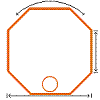
As previously mentioned, RG213 snug fits into the tubing material. This gave me the idea to actually slide in the coax cable in order to form a Galvanically isolated capacitor. Two reasons not wanting connect anything electrically to the aluminum: 1) it is nearly impossible to solder and 2) it will corrode in rapid rate.
As a result, the coax needs to be inserted in both open end of the loop, thereby closing the same capacitively. In principle this is like any other magnetic loop using a butterfly capacitor.
Just to remind you, this means that 2 capacitors are in series, i.e. they don't add up their capacities, they do this instead:
with Cr being the right capacitor and Cl the left capacitor.
There is a second benefit from series capacitors (in magnetic loops), they act a voltage dividers, thereby increasing the sparkling maximum voltage, allowing for higher power, in particular in the case of magnetic loop aerials.
Back to the capacitance story: the butterfly capacitor symmetrical, i.e. both capacitor have the same capacitance. What if the use variable capacitors having different capacitances?
Lets go through this with an example:
Assume that:
Cr = 10pF
Cl = 100pF
What will be the change in 1pF on either capacitor on the resulting capacitance?
- no change: (10*100)/(10+100) = 1000/110 = 9.091
- Cl lowered by 1pF: (10*99)/(10+99) = 990/109 = 9.083
- Cr lowered by 1pF: (9*100)/(9+100) = 900/109 = 8.257
And this is a fact I make use of in my most recent design: a magnetic loop aerial with an asymmetric series of capacitors.
Pictures say more than words:
 |
| Fig.1: asymmetric series of capacitors (purple) terminating a magnetic loop |
 |
| Pic.1: real life look of the terminating capacitance |
 |
| Fig.2: Dimensions used for the 20m band, blueish stuff being RG213 |
 |
| Pic.2: this is more than half a meter of RG213 dangling out the loop |
Of course, a magnetic loop aerial needs a primary loop:
 |
| Pic.3: primary loop |
Why are those dimensions selected?
As to the loop diameter, having a loop with a generic resonance not much above the future operating frequency allow for small capacitance values to terminate (tune) the loop. Having a low terminating capacitance lower the voltage across the capacitor and broadens the bandwidth of the loop.
The length of 4m of said material, when bent into a circle, deliver a natural resonance at about 15.5MHz. Starting from there, very little capacitance is required to resonate the loop at 14MHz.
The 70cm for the length of the "insert" were a lucky scientific a precise guestimate...
How to tune this loop and why is it asymmetric in capacitance?
Both these question seem unrelated, but they are not! The beauty of this entire design is found in asymmetry actually. Remember the section about changing the larger or smaller capacitors in a series of capacitors? The shorter end of the coax (when inserted into the tubing) acts like a "band set", the longer end like a "fine tune".
Inserting the coax entirely in a symmetrical fashion, the resonance drops to close to 9MHz, tuning here is very fiddly...
Having the coax in asymmetric configuration, the longer end provides relatively smooth tuning.
What is the bandwidth?
Well, I have not yet tested the aerial decently, but, first measurements with an MFJ-269Pro indicated that the loop, tuned to 14.060MHz is good for +/- 20kHz.
Certainly there are ways to calculate the bandwidth, the radiator 12mm has a circumference of 4m. There must be some web-application to evaluate such a loop (http://www.66pacific.com/calculators/small_tx_loop_calc.aspx) indicating a bandwidth of about 40kHz... (see below).
My plans for the loop are: QRP and PSK on 20m. Hence, I taped down the short end, as to have my band set. Of course, WSPR and QRSS are also in the reach of this loop...
This loop still is in experimental stage. For a more permanent solution, I will install an electrical box over the terminating capacitor, as to prevent water to collect within the tubing. For the same reason I may even drill a small hole into the bottom of the loop, allowing for drainage.
Concerning the dimensions of such a loop, 30m may still be an option. However, I rather see myself building this loop for the higher bands in the near future.
Results from 66pacific.com:
RESULTS:
Antenna efficiency: 68% (-1.7 dB below 100%)
Antenna bandwidth: 40.3 kHz
Tuning Capacitance: 50 pF
Capacitor voltage: 631 volts RMS
Resonant circulating current: 2.77 A
Radiation resistance: 0.223 ohms
Loss Resistance: 0.104 ohms
Inductance: 2.58 microhenrys
Inductive Reactance: 228 ohms
Quality Factor (Q): 349
Distributed capacity: 11 pF
Antenna "circumference": 4 meters
 |
Side length: 0.500 meters |
Comments:
The specified conductor length of 4 meters is OK.
Conductor length should be between 2.59 and 5.17 meters at the specified frequency of 14.06 MHz.
For highest efficiency, the conductor length for a small transmitting loop antenna should be greater than 1/8 wavelength (greater than about 2.59 meters at the specified frequency of 14.06 MHz).
To avoid self-resonance, the conductor length for a small transmitting loop antenna should be less than 1/4 wavelength (less than about 5.17 meters at the specified frequency of 14.06 MHz).
Input Values:
Length of conductor: 4 meters
Diameter of conductor: 1.2 centimeters
Frequency: 14.06 MHz
Transmitter power: 5 watts
