Showing posts with label qrss. Show all posts

Wednesday, April 22, 2020

60m Region 1 Crystal Combination

Sorry for having been silent for so long. There was a lot going on over the last few years.

Anyway, the present situation brought me back to Ham Radio and thinking of building stuff. However, I have to mention that this post should be considered more as a note to myself or inspiration of fellow RF designers, rather than a fully worked out recipe.

The topic of one of my next projects will be building some QRP rig for 60m. Over here in the Netherlands and in Region 1, we got a very small slot from 5351.5kHz to 5366.5kHz assigned as secondary service with a maximum EIRP of 15W. This is a range which appears to me to be almost ideal for building some QRP gear.
In modern times, we could use DDS systems to get us anywhere with anything, I must admit. In the older days, using combinations of readily available inexpensive crystals was the #1 choice for QRP.
Whilst having CW in mind, some of my thoughts my actually be useful for a side-band superhet design.

Here is what I found:

  • 15.360 MHz crystals for use in a VXO (or superVXO)
  • 10.000 MHz crystals and oscillators for BFO and filter stages.
To be honest, I just cooked up the idea and have not thought is through entirely. But here is what my mind came up right away.
As a side remark, subtractively mixing of crystal oscillators is a well known method of eliminating temperature drifts. So, effectively, this could lead to very stable designs, when done properly.

Transmitter
Option A is a canned 10.000MHz oscillator and push the signal through a 10MHz crystal in order to produce a sine wave.
Option B would be a regular crystal controlled discrete beat oscillator.
Mix any of option A or B with a 15.360MHz VXO to generate a 5.360MHz output signal. Should the pull be insufficient (not very likely at 15MHz) one could still use a superVXO.

Receiver
Here is where the concept presently struggles. 
Of course you would think building a crystal filter with inexpensive 10MHz crystals. However, this would probably exclude option A for the TX. Here is where the struggle lies, would it be possible to create a filter design with 10.000MHz crystals that pulls 600 or 800Hz away?
When using option B for the TX, of course, one would add a simple RIT design.

CW
You have seen me writing about two different options. Why bother, you might ask yourself. Well, to me, it is all about simplicity. 
For a mere transmitter, in option A, I might just use a canned 10.000MHz high precision oscillator and key just said oscillator, rather than a buffer stage for CW operations.  Experimentation will have to show how that sounds. In terms of simplicity, this would be pretty neat. Such a TX could be combined with some sort of SDR receiver or maybe a Polyakov direct conversion RX based on a 2.68MHz VFO.
Option B would allow for a fairly regular QRP CW transceiver. Nothing to write home about, however, this will certainly be a more complex design.

SSB
Obviously, option A is no longer available here. However, seen that it is recommended to use USB on the Region 1 assigned 30m band, it would be an obvious measure to use a pulled 10MHz BFO for both RX and TX. However, mind the mirror, we are subtractively mixing here.
Having in mind the upper portion of the 60m band, i.e. the weak signal band from 5366.0 to 5366.5kHz, option A might just come into play again. Mind you, QRSS & Co, don't mind about the sideband too much, as long as the operator knows what she/he is doing.

Over the upcoming days, I will work on a concept/prototype and hopefully will be able to report on some progress soon.


Wednesday, April 2, 2014

Finally: The PEx/Al/PEx Loop!

Yeah, that was a good one today. I took a couple of hours for tinkering and finally got to build my long planned magnetic loop aerial made from the recently discovered light weight copper substitute PEx/Al/PEx.

As previously mentioned, RG213 snug fits into the tubing material. This gave me the idea to actually slide in the coax cable in order to form a Galvanically isolated capacitor. Two reasons not wanting connect anything electrically to the aluminum: 1) it is nearly impossible to solder and 2) it will corrode in rapid rate.

As a result, the coax needs to be inserted in both open end of the loop, thereby closing the same capacitively. In principle this is like any other magnetic loop using a butterfly capacitor.
Just to remind you, this means that 2 capacitors are in series, i.e. they don't add up their capacities, they do this instead:
with Cr being the right capacitor and Cl the left capacitor.

There is a second benefit from series capacitors (in magnetic loops), they act a voltage dividers, thereby increasing the sparkling maximum voltage, allowing for higher power, in particular in the case of magnetic loop aerials.

Back to the capacitance story: the butterfly capacitor symmetrical, i.e. both capacitor have the same capacitance. What if the use variable capacitors having different capacitances?
Lets go through this with an example:
Assume that:
Cr = 10pF
Cl = 100pF
What will be the change in 1pF on either capacitor on the resulting capacitance?
  • no change: (10*100)/(10+100) = 1000/110 = 9.091
  • Cl lowered by 1pF: (10*99)/(10+99) = 990/109 = 9.083
  • Cr lowered by 1pF: (9*100)/(9+100) = 900/109 = 8.257
Very obviously changing the higher capacitance has less influence than changing the lower capacitance.

And this is a fact I make use of in my most recent design: a magnetic loop aerial with an asymmetric series of capacitors.

Pictures say more than words:

Fig.1: asymmetric series of capacitors (purple) terminating a magnetic loop

Pic.1: real life look of the terminating capacitance
Fig.2: Dimensions used for the 20m band, blueish stuff being RG213

Pic.2: this is more than half a meter of RG213 dangling out the loop
Speaking of dimensions (finally), I need to add that the loop conductor itself is made from precisely 4m of 14x2 PEx/Al/PEx (out diameter 14mm, wall thickness 2mm).

Of course, a magnetic loop aerial needs a primary loop:
Pic.3: primary loop
Dimensions for the primary have a thumb rule: 1/6 diameter of the radiator when placed very far from objects, 1/5 in average situations and 1/4 when used in doors. Mine is made from 80cm of copper installation wire, i.e. 1/5 diameter of the radiator. Of course is very easily exchanged when going indoors.


Why are those dimensions selected?
As to the loop diameter, having a loop with a generic resonance not much above the future operating frequency allow for small capacitance values to terminate (tune) the loop. Having a low terminating capacitance lower the voltage across the capacitor and broadens the bandwidth of the loop.
The length of 4m of said material, when bent into a circle, deliver a natural resonance at about 15.5MHz. Starting from there, very little capacitance is required to resonate the loop at 14MHz.
The 70cm for the length of the "insert" were a lucky scientific a precise guestimate...

How to tune this loop and why is it asymmetric in capacitance?
Both these question seem unrelated, but they are not! The beauty of this entire design is found in asymmetry actually. Remember the section about changing the larger or smaller capacitors in a series of capacitors? The shorter end of the coax (when inserted into the tubing) acts like a "band set", the longer end like a "fine tune".
Inserting the coax entirely in a symmetrical fashion, the resonance drops to close to 9MHz, tuning here is very fiddly...
Having the coax in asymmetric configuration, the longer end provides relatively smooth tuning.

What is the bandwidth?
Well, I have not yet tested the aerial decently, but, first measurements with an MFJ-269Pro indicated that the loop, tuned to 14.060MHz is good for +/- 20kHz.
Certainly there are ways to calculate the bandwidth, the radiator 12mm has a circumference of 4m. There must be some web-application to evaluate such a loop (http://www.66pacific.com/calculators/small_tx_loop_calc.aspx) indicating a bandwidth of about 40kHz... (see below).

My plans for the loop are: QRP and PSK on 20m. Hence, I taped down the short end, as to have my band set. Of course, WSPR and QRSS are also in the reach of this loop...
This loop still is in experimental stage. For a more permanent solution, I will install an electrical box over the terminating capacitor, as to prevent water to collect within the tubing. For the same reason I may even drill a small hole into the bottom of the loop, allowing for drainage.

Concerning the dimensions of such a loop, 30m may still be an option. However, I rather see myself building this loop for the higher bands in the near future.


Results from 66pacific.com:

RESULTS:
Antenna efficiency: 68% (-1.7 dB below 100%)
Antenna bandwidth: 40.3 kHz
Tuning Capacitance: 50 pF

Capacitor voltage: 631 volts RMS
Resonant circulating current: 2.77 A
Radiation resistance: 0.223 ohms
Loss Resistance: 0.104 ohms
Inductance: 2.58 microhenrys
Inductive Reactance: 228 ohms
Quality Factor (Q): 349
Distributed capacity: 11 pF

Antenna "circumference": 4 meters

Loop antenna Side length: 0.500 meters
Antenna diameter: 1.2 meters

Comments:
The specified conductor length of 4 meters is OK.

Conductor length should be between 2.59 and 5.17 meters at the specified frequency of 14.06 MHz.

For highest efficiency, the conductor length for a small transmitting loop antenna should be greater than 1/8 wavelength (greater than about 2.59 meters at the specified frequency of 14.06 MHz).

To avoid self-resonance, the conductor length for a small transmitting loop antenna should be less than 1/4 wavelength (less than about 5.17 meters at the specified frequency of 14.06 MHz).


Input Values:
Length of conductor: 4 meters
Diameter of conductor: 1.2 centimeters
Frequency: 14.06 MHz
Transmitter power: 5 watts

Saturday, January 18, 2014

The E-Probe Got a New Location

The regular reader of this blog may know, that I am using different aerials for my grabber. All on a longer term. First it was the DCTL, than it was the E-probe (aka. modified mini-whip).

For many months, the E-probe was just dangling from the edge of my upper roof, which screened South by a good part.

Since some weeks, I put it on my upper roof. As soon as it was up, of course we had a solar storm and condx went down. Even with condx up again, not a single DX was received. I figure this would be caused by the rather low position of the E-probe. Reason for that decision was to be safe in storm. It can actually blow a bit here in South Holland.

Here is how this setup looked:
E-probe, just above the edges of the roof


Today, I decided to raise the E-probe by 1m, by adding an additional piece of PVC pipe to the construction. Originally, I wanted to use a straight coupling piece to do that, but that would have meant to pay a visit to the hardware store. In garage, where I kept the piping, I found a matching T-coupler. This could be used to the advantage of the setup!
Why not feeding the coax-cable through the stand, a guide it out at the T-coupler?

Of course, first I had to take thing apart, in order to feed the coax through the stand's tubing.
Disconnected and in pieces
DONE!
Now to the first impressions. Of course I did not shutdown the grabber during the process, so one can see a clear "before and after" (and also some in-between).
Before
During (and after)
After
 What happend? (times in Zulu/UTC)
  • 13:26 - I disconnected the coax from the E-probe
  • 13:30 - reconnected the coax and arranged stuff
  • 13:33 to 13:34 - cleaning of the BNC-connector 
  • 13:34 - I left the roof
My first impression is, that I am able to receive 3 QRSS stations, just minutes before, I did not receive any. 

I just hope that the leverage of the higher E-probe will not cause the entire thing to be blown off the roof by the next breeze.

Update:
The relatively lightweight bricks are now replaced by heavy concrete garden tiles. This should do, even when storms should come up.
The bricks will now be used for another flower pot heater...

Saturday, January 4, 2014

Subharmonic 30m RX Design

30m QRSS Grabber Receiver


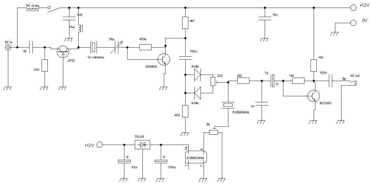
The basic design is a mix of ideas gathered from pa2ohh, the ARRL Handbook and publications made about the subharmonic mixer of Prof. Polyakov (ra3aae).
Since I am a really lazy dawg, thinking came first...

What we want to observe is 10140000 to 10140100Hz. Let's see what is available.... 10.140MHz crystals, close, but too close for comfort. Pull those crystals, and oscillators will become less stable. 10.125MHz crystals... too far off! 10.135MHz, closer, possible, but still pretty far off; 5kHz, oh my goodness!

But we also got really cheap and well available crystals and oscillators (!) at 5.0688MHz. Multiply by two and we are at 10.1376MHz, that's just 2.4kHz off the lowest frequency we want to receive. 2400-2500Hz also is in the comfort zone of any random soundcard at even low sampling rate.
To use this particular frequency, all we need to do is, multiply by two, or in other words, double it.

Jan (pa9qv/oz9qv) pointed me towards Prof. Polyakov's mixer, also known as the Russian mixer. Great readings from late la8ak, check this out: http://noding.com/la8ak/c21.htm

Thus, there we are, ultra-cheap 5.0688MHz CMOS-oscillators combined with a Russian mixer receives the 30m-qrss-band at about 2.4kHz. Let's design something!


Final design

A Polyakov mixer is supposed to work best with a sine signal. The CMOS-oscillator's signal however looks more like a squarewave, involving a lot of harmonics. The easiest and cheapest way, as it seemed to me, to transform that into a sine, is a crystal in series resonance.

The unwanted lower sideband has been taken care of by including a 10.140MHz-crystal behind the preamp.
Behind the filter, a RF-amp is added to compensate for losses. Due to this, the filter response is now shifted up again, I will look into this, but for now, I will let the receiver run and collect data/info.
As promised, I looked into it, shifting a crystal up is done by capacitive load. Reducing this load will bring the crystal closer to its series resonance frequency. To be a little bit on the adjustable side this time, I added a trimmer found in my junk box. I thought it would have a max. capacity of 18pF. This trimmer allows for adjustment of the crystal filter pass band frequency.

Consideration for operations w/o the filter: we are looking at a bandwidth of 100Hz and the received LSB will be (about) 10135100Hz to 10135200Hz. I figure, there is just the occasional Feldhell QSO, but other than that, the LSB range of the DSB receiver seems to be an empty spot.

A jumper is added in order to enable support of an active antenna via coax cable. The ideas for an active aerial are floating presently. It will be a shielded resonant loop with a preamp, that's for sure. The loop will be made from "YMVK-as 2x2.5mm²" which is underground twin-lead mains cable, doubly shielded. In an earlier experiment I successfully made a 40m-75m RX-loop from that stuff.

Subharmonic 30m direct-conversion receiver
 

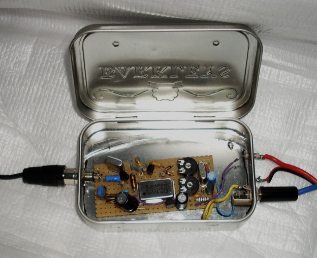
Photo of the 30m direct conversion receiver


The actual receiver, as running for many years

Monday, December 9, 2013

How to tune the suburban sub-harmonic receiver


Some help to adjust the balance and drive of the sub-harmonic receiver used in my grabber (dashed lines indicate 0.7V cut-in voltage for Si-diodes, V is mixer drive voltage).

1) Mixer correctly driven: Within one period a single diode opens for exactly 90 degrees (red). Within the same period, the other diode opens for 90 degrees (blue), while the rest of the time, the diodes are both closed (yellow). As you see, the first diode opens at 45 degrees, that is very important! You also see, the entire mixer is open twice within one period; that’s the trick of the frequency doubling. Any off-balance shift will produce harmonics, which you can’t get rid of.


2) Let’s have a look at the mixer being extremely out of balance. In this example, -0.7V, which would open the second diode, is never reached, hence, this diode will never open. Consequently, the mixer will open once in a period, thereby not doubling the frequency. Still, due to under-sampling, some signal will be received, however, this is essentially a DC-RX for the LO-frequency. Actually, one can make use of this, e.g. for a 14MHz sub-harmonic receiver, which, when adding the correct off-set, will turn into a 7MHz DC-RX (either with a second crystal filter, or non at all).

3) And now, the mixer in balance, but over-driven. This will let a lot of signal through and will actually also double the frequency. However, the phase of the mixer is now totally off, i.e. asymmetric. This will produce a lot harmonics, so the receiver will receiver on many multiples of the local oscillator.


Actually, it takes a bit of patience to find the sweet spot in such a receiver. For me, it works well, for many years by now.

Saturday, October 26, 2013

QSO?

What is a QSO nowadays? Not sure, in particular when talking QRSS.

The latest fashion seems to communicate via an online grabber. This this a QSO?
I don't think so, for the following reasons:
  1. both stations have contact to the grabber, which is rather an automated SWL connected to the internet
  2. there is no wireless link from the online grabber to neither of the two stations
  3. the online grabber does not repeat a signal per se
However, all in all, I believe using a grabber to communicate is somewhat fun, since the communication is somewhat full-duplex.

What amateur radio is concerned, there still is the issue of dependency of many non-amateur communication channels, namely the ISPs of the three involved parties.

Wednesday, August 14, 2013

12m XTAL Controlled QRSS / WSPR / QRP / SDR

In a previous post, I described the use of CD-crystals for 17m weak signal operations. This post is attempting to do the same but for the 12m.
The crystals I am mentioning here are also used in CB-rigs, although harder to find. Here's would be a possible source.

QRSS: 37.340MHz => 12.446MHz x 2 = 24.892MHz
QRP/SDR: 37.350MHz => 12.450MHz x 2 = 24.900MHz
WSPR/QRSS: 37.395MHz =>  12.465MHz x 2 = 24.930MHz

SW+ 40 possible WSPR/QRSS mod

Regular readers of my blog will know that a PSK-Warbler could easily be modified into a 40m WSPR transceiver. I believe that Dave K1SWL even mentioned this mod during his talk at the FDIM-QRP-Convention.
Very unfortunately, the Warbler has been retired later that year. It seems the days for easy 40m transceivers are over.

However, there is hope, the 40m SW+.

The trx employs a 4MHz crystal filter for reception, since the SW+ is a superhet A1A transceiver, there is no if-filter in the tx-train.
The transmitter consists of the VFO, and up-converter (NE612), a link-filter, linear buffer and driver and a class-C power amplifier.

This is what I see, could be done to the rig... please grab a circuit diagram (can be found on K1SWL's homepage).


Concept


We want to have zero-beat at 7038.6kHz. So the sum of intermediate frequency and local oscillator should end up there. With the 4MHz intermediate frequency the kits comes with, we would need a frequency source of either 3038.6kHz or 11038.6kHz. Both are somewhat hard to reach on standard crystals.
Now, lets have a look what get's us close...
Lets check out the options:
  1. 5.000 + 2.048 = 7.048
  2. 5.200 + 1.843 = 7.043
Option one will require penning down the 2.048MHz crystal, however would open the option of using a 2.000MHz crystal for the lower band edge QRSS range. Additionally, a 2MHz ceramic resonator oscillator would enable operation in the regular CW portion of the 40m band.
Option two would probably work by just severely pulling of a 1.843MHz crystal.


VFO


This is were the mod begins. The VFO should be skipped; an external xo will be doing this job. Having the local oscillator external will provide some advantages for QRSS operations. First of all, temperature stabilization should be applied. Secondly, one may consider switching between several crystals.
Most importantly, an extra 7dBm output should be added for a transmit DSB modulator.


BFO

In a side-band transceiver, an offset between the BFO and the up-converter is not wanted. In a CW transceiver, one wishes to have an offset of about 800Hz between RX and TX. Since the SW+ is a CW transceiver, we would like to get rid of the off-set. The easiest way of doing this would be to buffer and feed the BFO into the up-converter.


Receiver

The receiver is pretty much were we would like to have it. All crystals should be changed according to the mod you would like to perform.


Transmitter

This is were the choice of option will become important. Buffer and driver look just fine, however, it is definitely required to convert the PA from class C into class AB for linearity. It might be easiest to just design a linear PA, potentially external, and feed the buffer into it. Another option would be to merge designs. Genesisradio.com.au once sold a qrp-transmitter kit, the Q5, which was equipped with a 500mW class A linear PA. The PA design itself genesisradio took from their SDR-TRX.

Sunday, January 20, 2013

PSK Transceiver Kit

Very unfortunately, but understandably, Dave (Small Wonder Labs) has discontinued his marvelous PSK-series transceivers.

Lucky for us, there is another kit vendor, who's kits have the potential to replace the ones of Dave.
Have a look at the KN-Q7A kits.

The 20m KN-Q7A operates with an i.f. of 4.194MHz, using a ladder filter made of standard xtals. The transceiver makes us of a moderately pulled VXO of 18.432MHz. All parts a relatively standard and well known, apart from a couple of inductors. The design makes use of subtractive mixing, which increases stability.

Here's what we can learn from Dave's PSK-series, the combination of standard crystals to result in an operating frequency near enough to the PSK bands.
  • 30m: 4.000MHz + 6.144MHz
  • 20m: 5.0688MHz + 9.000MHz
The only difference to the KN-Q7A is that additive mixing is used. 

The 40m KN-Q7A involves two different i.f., dependent on the frequency range ordered, either 8.467MHz or 8.192MHz. The l.o. will make use of any of those frequencies: 15.360MHz, 15.418MHz, 15.500MHz, 15.536MHz or 15.570MHz. I have not yet figured out a combination to reach 7.040MHz, however, I am sure that one can be found.

Further, I am convinced that the design can easily be adapted to the 80m band. Think of 10.000-6.400 for starters.

As to QRSS/WSPR:
  • 30m already cover the mod above
  • 15m 4.000MHz i.f. and 25.000MHz l.o.
  • 15m WSPR:  4.096MHz i.f. and 25.000MHz l.o.
  • 20m could be reached by 4.000MHz i.f. and 18.000Mhz l.o.
  • 20m WSPR: 4.096MHz i.f. and 10.000MHz l.o.
  • 40m best option would be 4.000MHz i.f. and 11.000Mhz l.o. (alternatively 11.059Mhz)

Monday, April 2, 2012

Light Communications Idea

Once again, the entertainment industry inspired me to this one. In stage illumination, the most recent development is the use of multi-color LED spots and washers. Those devices contain either three or four differently colored groups of ultra-bright LEDs. Controlling of the spots or washlight is usually done a serial protocol called DMX, by so called DMX-controllers or DMX control software.

In stage lighting language one controls different settings of "fixtures" (the lighting devices) and stores this control settings in "scenes". The scenes than can be called either manually or automatically as a sequence called "chase". The frequency in which the scenes of a chase are being called usually can be set by a sliding fader.

So, what's the trick about all this and where is the link to amateur radio?
Very simple, in long range light communication or cloud scatter experiment, usually QRSS is used. Now the link should be obvious... the fixture(s) are, very obviously, the light source(s), while the DMX-controller serves a beacon keyer.

A simple series of unmodulated dots (A1A) can be programmed with the following 2 scenes:
  1. red on all fixtures to 100%
  2. red on all fixtures to 0%
The next step would be to program of a chase of scene 1 and scene 2.

Unmodulated signals may be hard to discriminate. However, with the strobe function, the entertainment industry offers a solution to this problem. The strobe will create sidebands in the known fashion.
So, for a modulated signal (A2A) the following scenes can be used:
  1. red on all fixtures to 100% with a fast strobe
  2. red on all fixtures to 0%
Again, the chase would simply repeat scenes 1 and 2.

In order to know what I am writing about, I actually bought some material at a local pro-audio store:
Reasons for the decision on just those devices:
The washlight can be controlled by either 3 or 7 DMX channels. 3 channel resemble the control of the red, green and blue LED groups. 7 channels include said RGB-controls and some more stuff, which can be found on the respective webpage (#4=hue, #5=strobe, #6=color cycles, #7=luminance).
The lighting controller employs 8 faders to control 16 channels before switching to another "fixture" (i.e. bank) is required. This 8 channels fader control comes handy to control 7 channels of the SlimPar 38 or (and that's another trick) 3 channels of 2 SlimPar washers. In the latter case, two devices are controlled by a single fixture channel.
Just for the interested: the trick is the address of the washer or spot. The address of the first device (officially called fixture, but this can be confusing here, hence, let's call the individual washers or spots "devices" for now) will be "1".  If the device is using 3 channels, the address of the second device could be "4". In this case, provided the above mentioned controller is used, the first 3 faders would control the first device's R, G and B groups and faders 4, 5 and 6 would control the second device's R, G and B groups. The advantage, the two devices are now dealt with as a single fixture.
Advice: With a 16 channel controller (as the one I am using) one could potentially control 5 3-channel devices, however, the assignment of the fader will be rather confusing. Therefore, I recommend controlling 4 3-channel devices only. For sake of convenience, I would assign the second device to address (channel) 5, the third to address 9 and the fourth to channel 13.

Back to QRSS. Even the cheapest of DMX-controllers with the cheapest of LED-spots would make a real nice light beacon setup. OK, I went for something more sophisticated... since I see a secondary use in my light beacon setup... just in case I want to through a party, I now have a club-worthy lighting setup.

Concluding, there may be "red only" devices. However, stage worthy multi-color devices would even allow for multiplexing, depending on the receiver filters. The ones I use through out 1500lx @ 1m each, all LEDs engaged (at a power consumption of about 20W). Since I bought 4 (for good measures) that would be 6000lx @ 1m in white or about 2000lx using just one color.
Now I need to work out some receiver concept.

Thursday, August 25, 2011

Half-wave 27MHz Antenna as Broadband Vertical

Years and years ago, a friend of mine gave me a (brand new) half-wave CB antenna. Well, I have never used it, for the reason of not being QRV on 11m. For 10m I had my double bazooka, so there was no need for it. Now that it has been sitting in a corner for a while, I thought, maybe it could be useful for something else. Some else as in broadband vertical...

Now, let's have a look how those things are built:

aerial schematics
This drawing is not made by me, however, it nicely sketches what the following photographs of my very own version of that antenna show.

all still in one part


taken apart
What we have is the cavity and the transformer that was sitting in it. The air core transformer has got a winding ratio of 7.5:2. I figure, using a ferrite or iron powder toroid would improve performance on lower frequencies.
The cavity measures 35mm in diameter, having a depth of 24mm. This clearly offers enough space to house a smaller toroid transformer.

At this place, I would like to remind you of the BB7V (Diamond) having an UnUn transformer with (resistive) termination shunt. This vertical would be 6.7m tall. The regular 11m half-wave vertical could possibly be stretched to a tallness somewhat beyond 5.5m. Close enough to me.

Now let's think... for QRP work a T80-2 would make an ok UnUn. With some luck, transformers with a T130-2 core could possibly be squeezed in the cavity, if made carefully.
Reconsidering the BB7V's terminator, would I put one in there? Only if I would be using this aerial for QRPp only. The base of the CB-aerial is made from plastics material, which is not able to conduct any heat. Hence, heat created inside the cavity would never be dissipated. For QRSs/QRPp, the resistive terminator is a very appealing option, in particular since for such power levels, a T50-2 transformer would offer sufficient empty space for the terminator.
A T130-2 would possibly be good for a regular 100W rig. However, in a worst case, 50W of heat have to be dissipated, hence, some cooling of the termination would be required, therefore, this is a no-go. Some adjustments and selective use of bands would still be an option for such an arrangement.
Personally, I am very tempted to try a version of a T68-2 transformer (not sure about termination yet), in combination with my IC-703. This is somewhat of a compromise...
Should I ever again get into QRPp/QRSs/WSPR/WSJT/ROS actively, my preference would be the small transformer&terminator option.

Additionally, I figure, it could be of use to add an additional Al-pipe of about one meter to the top of the vertical. This will result in a total length of about 6.4m and a further distance to a quarter-wave on 20m, without getting too close to a quarter-wave on 30m.

There you have it, a new life for a cheap half-wave 11m vertical.

Monday, May 23, 2011

QRSS Studies - the Results

Seen that there is no more for me to investigate in QRSS, other radio topics will soon become more relevant to me, and also to this blog.


The results I can report on QRSS
  • You can operate a decent visual grabber in very densely populated regions. One will see the neighbours' TV sets, which in many cases is not more than just annoying.
  • The reception of WSPR is not affected by urban noise, low profile and even indoor antennas give good results.
  • There is no need to occupy your expensive main rig or a professional receiver, a cheap and cheerful home fixed frequency RX does the jobs.
  • Setting up an online grabber is something that anyone with internet access can do, no excuses here. The demands on the respective computer are minimal. An Intel ATOM can easily operate two grabbers and WSPR (rx in my case), have a third instance of speclab running, be a print and file server and operate winamp for internet radio... all at once.

Conclusion I learned from my experiments, on-air and off-air
  • There are many more transmitting stations than receiving ones.
  • Despite my efforts to motivate the installation of additional grabbers, there are still only a few.
  • Operating a grabber blocks other activities, at least on the bands the grabbers are active on.

What I miss in QRSS is interaction, consequently, I will for the time being cease QRSS activity until further notice.

My focus for the time to come will be on data modes such as PSK500, ALE, etc.
Another thing that crossed my mind occasionally, going QRO with some homebrew kit. Saying QRO, I mean QRO, i.e. legal limit. It is not so much the urge of being heard, it's more the design challenge here.

Thursday, April 21, 2011

Day to Night Transition

Just a spectrum I would like to share. It nicely shows the transition from day time propagation to night time propagation.


Wednesday, April 6, 2011

17m XTAL Controlled QRSS / WSPR / QRP / SDR

Sorry for having been silent for a while. Some new thought, although not entirely mine, I believe sharing it this way would be more than appropriate.
The idea about the frequency generation is borrowed from DJ1ZB. Ha-Jo uses CB crystals on their fundamental and doubles the result.

Doubling sounds very much like two things I previously disclosed on this blot, namely, the subharmonic direct conversion receiver (e.g. this) and the subharmonic I/Q-SDR (see earlier posts on the SDR and possible frequencies).
Both designs rely on a local oscillator on half the operating frequency.

Concentrating what could be interesting for QRP, QRSS and WSPR, lets have a closer look to the available crystals.
  • 27.105MHz (12T) => 9.035MHz x 2 = 18.070MHz
  • 27.135MHz (15T) => 9.045MHz x 2 = 18.090MHz
  • 27.155MHz (16T) => 9.051667MHz x 2 = 18.103333MHz
  • 27.165MHz (17T) => 9.055MHz x 2 = 18.110MHz
The frequency generated with a 15T-XTAL appears to be ideal for I/Q-SDR since the whole CW & Data & beacons range will be covered by 48kHz sampling rate. Have a look: difference 18.090-0.024=18.066 and sum 18.090+0.024=18.114.
Additionally, 18.090MHz is the quite close to the QRP frequency, a subharmonic direct conversion receiver would be an obvious choice, so would be a transmitter with a doubler...

Very obviously, the other frequencies are directed more to QRSS and WSPR. I am not going into the QRSS feature here, it is kinda trivial (see above).

Remaining topic: WSPR. The frequency produced by the 16T-XTAL is very very close to the WSPR "dial frequency" 18.1046MHz. With a Pierce oscillator the tiny amount of 633Hz upwards pull should not be a big deal; remember, on half the frequency, one only needs to pull half the distance.
RX: subharmonic direct conversion.
TX: subharmonic mixing of the local oscillator with an audio signal should create a DSB signal... that's the theory... I have not yet tried it yet, however, I fail to see any reason why this should not work.

Friday, March 4, 2011

6m QRSS

This is an extremely easy one. Most QRSS operators once built a 30m MEPT. There is an easy way to recycle those transmitters for 6m. With a converter circuit running a 40MHz oscillator, a 10.140MHz MEPT would be right away transmitting on 50.140MHz. Not too bad, I figure. A NE612 would probably be the easiest and cheapest way to get there this way.
Alternatively, a subharmonic mixer (two anti-parallel diodes) on a 20MHz oscillator would be even easier to build.
There are canned oscillators for 40MHz and 20MHz available, not to mention those cheap crystals.

Wednesday, March 2, 2011

2m QRSS

Something I was thinking of occasionally, QRSS on VHF, UHF, SHF and EHF bands.

Lets first start with a band that is accessible to all of us, the 2m band.

A short chat with Dave (G7UVW) brought up two frequencies of interest.
  • 144.070 MHz
  • 144.4905 MHz (WSPR)

Both QRGs can be reached with CB-TX-crystals on their fundamental frequency and doubling the signals a couple of times. 9.x MHz will have to be multiplied by a factor of 16. With a little pull and the right oscillator circuit, this all should be fairely easy.

144.070 MHz
Channel 5T (27.015MHz) will be, very obviously, be 9.005MHz on the fundamental frequency. The resulting frequency on the 2m would be 144.080MHz. A little harmless down pull to 9.004375MHz on the fundamental will get us to 144.070MHz.

144.4905 MHz (WSPR-QRG)
We got two options here,  channels 11T (27.085MHz) and 12T (27.105MHz).
11T would require a Pierce oscillator which oscillates above the series frequency of the crystal. The fundamental of 11T is 9.028333MHz, while the required frequency for the target-frequency would be 9.03065625MHz. The difference of 2.323kHz is not problem to a Pierce oscillator at all.
12T will provide a 9.035MHz signal. The pull of 4.344kHz to 9.03065625MHz is doable, could however result in a less stable oscillator.

Put the design into practice seem not to be a great deal, however, frequency stability is a great deal here. So, I figure, good temperature stabilization is in order. The rest is in fact pretty straight forward. I do have to admit that the first ever ham-radio transmitter I built (age 15, just licensed) was a 144MHz A1A TX, based on a CB crystal and BF199 transistors.

Monday, January 31, 2011

NVIS QRSS

This could be a fun one to do: dual band NVIS QRSS.

Not sure what NVIS is? Please have a "google" to find out. There is a lot of excellent documentation available.
The only bit of info about NVIS I would like to point out in the post would be the fact that the 40m band is good during the average day and the 80m band is good for the average night. Running both in parallel could show some interesting daytime nighttime transitions.

Due to the harmonic nature of the 80m and 40m bands the easiest approach for a transmitter design would be to build an oscillator for either band and generate the other frequency by division or doubling. The downside here: shifts and offsets would also be divided or doubled.

A receiver also could make use of a single local oscillator. Here the most simple design would be a regular direct conversion mixer for 80m and a subharmonic direct conversion mixer for 40m. The respective audio frequencies could be fed into one single stereo sound card using left and right channels.

Frequency-wise, there are two obvious possibilities.  Both have pros and cons:
  1. 3500400Hz & 7000800Hz
  2. 3579545Hz & 7159090Hz
The first option will make this sort of QRSS activity visible in grabbers as presently operated, it is however, due to the price of the crsytals more expensive than the second option.
The second option uses frequencies for which very inexpensive crystals are available, the big pro on the second option would be that is will enable many more hams to operate a transmitter legally (the ole novice story).

By now, you may have asked yourself why crystals still play a role here. Well, not so much for the transmitter, although they make nice filters for oscillators using digital gates. For a possible receiver those crystals would make ideal narrow front-end side-band filters, which are in particular important when operating in the middle of a busy band.

Want something more complicated?
What about a "superhet" design? With center (intermediate) frequency of 5.250800MHz and a 1.750MHz local oscillator the mixing products would be 3500800Hz and 7000800Hz. When shifting the intermediate frequency, both the 80m and the 40m frequencies will shift by the equal amount in the same direction, that's kinda cool!
Now to the tricky business how frequencies could be generated. Lets start with the easy one. 1.75MHz is subharmonic to 3.5, 7.0 and 14.0MHz. The first two call for trouble since those are too close to the final operating frequencies (*). But what about 14.0MHz? Crystals and even oscillators are available for this one! A division by 8 (ripple counter) will result in a very stable 1.75MHz local oscillator.
And here is the challenge: 5.250800MHz. There is a crystal for 5200kHz, but a 50kHz pull is too much and grinding is a tricky business. There may be a 10.5MHz crystal available, somewhere... As a last resort, a DDS would possibly do a superb job. This however would also be the most expensive solution.
(*) Problem for the TX, solution for the RX, subharmonic to 80 and 40 and the same time!

Want something even more complicated? No problem! That one is so overcomplicated, that is should rather be seen as experiment in thought. What about SDR? Take a 10m QRP crystal (28.060MHz). This frequency is perfect for a 40m SDR, center frequency: 7.015MHz. A quadrature local oscillator can be derive by a division by 2, resulting in a 14.030MHz local frequency and a 3.5075MHz SDR center frequency. For reception, 2 stereo channels are needed and to provide I and Q for both bands. TX in such a case could be done by either individual audio frequency generators w/ 90 phase shift networks or in a way similar to the LO, with a 56.9kHz generator.
As I said, the SDR is somewhat hypothetical, not practical in any way....

The superhet TX design presently appears to be favorable, together with a subharmonic direct conversion receiver for 80 (1.75x2) and 40 (1.75x4).

Friday, January 28, 2011

4MHz - the Magic QRSS I.F.

Although the QRSS-community seems not to be as technical as it used to be, some thoughts about the matter from my side.

Some OM, again I am writing about novice/foundation/newcomer-lis, may not be allowed the lower band edge. But still, most activity takes place at those spots.

I asked myself, if I could find crystals to suite both needs. You will find some combis for one or the other option on this blog.

Meanwhile, I believe that 4.000MHz is the ideal I.F. for QRSS. Here's what can be done (more or less easily):

600m 4.5025MHz-4.000MHz=(27.015/6)MHz-4.000MHz=502.5kHz
The trick here, use a CB transmit (overtone) crystal for 27.015MHz (5T) and operate it a its fundamental, i.e. 9.005MHz. A division by 2 (flip flop) will end up at 4.5025MHz. A VXO at 9MHz may be pullable by a few kHz, hence, we may be able to cover a substantial portion of the present 600m hamradio band.
Should a future allocation be somewhat higher, there are many other CB-TX-XTALS available.
Should a future allocation be somewhat lower, there are many CB-RX-XTALS available.

NAVTEX 4.5175MHz-4.000MHz=(27.105/6)MHz-4.000MHz=517.5kHz
Essentially the same as above... the crystal being a 12T. For those who are not aware, there is maritime navigational (and weather) information transmitted on 600m, to be precise, 518kHz (international frequency) in FEC.
NAVTEX also knows a local frequency, which is 490kHz. This frequency is reached with a 39R (26.940MHz) xtal.

80m 4.000MHz-500kHz=3.500Mhz
500kHz can easily be generated from a 4MHz signal by dividing the latter by 8 (ripple counter). Running a 4MHz Pierce oscillator, the generated frequency will be above the 4MHz series frequency. Assume we generated a frequency of 4001kHz, 1/8 would be 500.125kHz, resulting in a mixed QRG of 3500.875kHz (TX).
For RX, a tweaked (fine tuned) L.O. can be used as B.F.O. to provide a reasonable beat for reception.

40m 4.000MHz+3.000MHz=7.000MHz
That would be the lower band edge solution... further comments here... however, there are better options!

40m 11.000MHz-4.000MHz=7.000MHz
Again the lower band edge, however, this is subtractive, therefore, temperature drifts will not add up but rather cancel (or at least reduce another).

40m 11.059MHz-4.000MHz=7.059MHz
This QRG is open to novice/foundation/newcomer-license holders! Temperature drifts will not add up but rather cancel (or at least reduce another). The frequency is at the upper edge of the 40m data segment, I believe, it is an ideal playground for testing all sorts of modes.

30m 4.000MHz+6.144MHz=10.144MHz
The classical 30m QRSS frequency is in close range. A local oscillator will have to generate a frequency of 6.139Mhz, which is reachable by either pulling of penning of a 6.144MHz standard crystal.

20m 4.000MHz+10.000MHz=14.000MHz
This is a no-brain-er! Just run a 10.0MHz LO.

20m 18.000MHz-4.000MHz=14.000MHz
This is a no-brain-er having improved temperature behavior... subtractive...

17m 4.000MHz+14.080MHz=4.000MHz+2x7.040MHz=18.080MHz
Here, the local oscillator would be sub-harmonic. 7.040MHz is just one example of many possibilities opened by crystals available for the 40m ham-radio band.

15m 25.000MHz-4.000MHz=21.000MHz
This again is a no-brain-er having improved temperature behavior... subtractive...

10m 4.000MHz+24.000MHz=28.000MHz
This is a no-brain-er...


10m 4.000MHz+24.000MHz=4.000MHz+2x12.000MHz=28.000MHz
Subharmonic.


Please feel free to add some ideas as a comment!

Monday, January 17, 2011

28322 Beacon Net Receiver

With the prospect of the upcoming activity in the present solar cycle, it is about time to think of a receiver for the (Italian) 28322(kHz) beacon network.
Due to the nature of those transmitters, the frequency range we want to be looking at is something like 3kHz, maybe 4kHz, i.e. 28320 to 28324kHz.


Now that the task is defined, let's move on and look at the obvious design involving inexpensive parts.

The xx322kHz frequency immediately makes me think of 14.318MHz crystals to form a filter for the intermediate frequency.

With an intermediate frequency of 14.318MHz, a local oscillator should create a frequency of 14.00xMHz. A local oscillator that close to the intermediate frequency will however put unnecessary strain on the IF-xtal-filter and even could end up clogging up a/the IF amplifier. I further believe that LO and BFO being so close is not such a good idea.
Solution to said problems: a local oscillator at 7.00xMHz (crystal easily available) hooked up to a subharmonic first mixer (pair of anti-parallel diodes). The intermediate frequency stage would be blind to 7.0MHz LO stray.

With the mixing all sorted, the next thoughts need to be spent on filter design. A bandwidth of 3, maybe 4kHz, makes a ladder filter a hard task, in particular since such a ladder filter would require quite some amount of poles. Even being harder to make, I figure a lattice filter would be the best option here. Lattice filters however require pairs of matched crystals being a some kHz apart. That is where the work sits in. One pair of 14.318MHz xtals can be selected by measuring/matching the series frequency of stock xtals. The other pair will have be to created by penning down two xtals to the exact same frequency.

For the BFO and the product detector the most obvious choice would be the NE612, just the way one would use it anyway.


Bored of QRSS?
There could be another use for the setup: an SSB phone RX, TX or even TRX. The important bit here, the bandwidth of the crystal filter should be around 2.4kHz. Such a bandwidth is easily available with a ladder filter, however, a lattice filter would give a better response.
Very obviously having a single channel SSB radio at a frequency where beacons beep around the clock is not the best of ideas. So, the LO will have to employ a different frequency. Luckily, many crystals are available for frequencies in the 40m band, e.g. 7030kHz, 7040kHz etc., hence, channelized or VXOed rig is no problem at all. Taking things further, a VFO could be on the wish list. And there is just a perfect option. The famous NE612 (SA612,NE602,SA602) can be configured to operate as a frequency doubling ceramic resonator oscillator. With a pulled down 3.58MHz ceramic resonator (avoid 3.58MHz!), a good portion of the 10m SSB range will be available.

At this place, I would like to thank Jan (PA9QV/OZ9QV) for triggering my thoughts about a 10m upper side-band design with the simple question "do you know a combination for 28322?" :-))

Friday, December 17, 2010

600m QRP TX update

It is about time to hurry up. Just a few more days and my 600m permit will have expired. As my energy slowly seems to be returning (don't ask what drained it - the regular reader may have a clue though), my soldering iron heats up more regularly. Today, the last drips of solder are dropped and the 600m exciter (see earlier post) has been given a "power stage", namely a 74HC240 operated at 8V.

Just applied some power, no keying yet... neither an aerial, just a few centimeters of wire. Still my grabber's AGC was pulled (tx-ing from ground floor through two reinforced concrete ceilings).


The spectrum shows DI2AM at 505180Hz. The signal at 503200Hz (1955z) would be me testing.
The HC240 developed slightly elevated temperature. I guess this is normal when running it at 8V. I said, the signal was not keyed, and it wasn't, however, I was handling the PCB, feeling temperature etc, hence the variation in signal strength.
I hope that, later 2nite, I will have hooked up a QRSS keyer to the transmitter and have it wired up to an aerial (I figure that will be the original Plumbtenna).