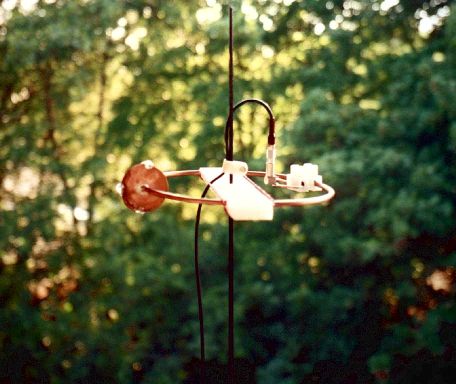
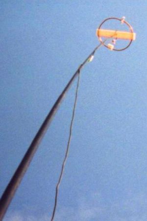
2m omni-directional antenna
(Squarooka - squared bazooka)
Concept
Sort of similar to the one of the 6m
omni. Instead of using twin-lead, this design makes use of a more or
less regular double bazooka antenna (coaxial dipole). Your attention
shall be drawn to the available standart literature, such as Rothammel.
In order to "compute" the dimension, Karl Rothammel mentioned that the
total length of the dipole shall be 95% of the free-space wavelength.
The short-circuit bridges (closing the folded dipole) are to be placed
at a distance-fraction being equal to the velocity factor of the coax
cable used, which will be 66% using RG-58 or RG174.
Some Simulations....
No sofisticated simulations have been done on this aerial... Just to
give a short impression what can be expected, a very rough simulation
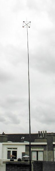
using "real" ground setting with an antenna height of 9.5m (corresponds
to a height gained by a
DK9SQ
"fibreglass telescope tower").

the horizontal directional diagramm

and for completeness, the vertical diagram too
Dimensions used for 144.350 MHz
Material used:
|
RG - 58
C/U
|
Total length RG58:
|
98.6 cm
|
Length
of one
dipole leg:
|
49.3 cm
|
Distance feed to short:
|
32.5 cm
|
Based on a free-space wavelength of:
( 299.79 / 144.35 ) m = 2.0768 m
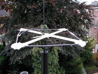
Have a closer look
... and identify my favourite materials. The cross is made of some
strange PVC profile this time. You might also recognise one
short-circuit bridge on the front right of the square.
|
|
Construction
The difficult part in building a double bazooka antenna is cutting the
coax. More precisely: NOT cutting throught vital parts of the coax
cable, i.e. the braid.
As shown in the image below, the outer (black) insulation and the
shield have to be cut, preferably w/o cutting into the dielectric...

This is the way I usually do these sort things:
- scarsify the insulation with a sharp knife at the first side of the feed point,
taking care not to cut through the black polymer
- bend the cable at the
cut, which will cause the insulation to torn apart precisely at the cut
- scarsify the insulation with a sharp knife at the second side of the feed point
- cut in a straight line from the first to the second edge and peel
off the insulation
- wind one turn of 1mm solid copper
wire (approximately 1cm long) around the shield on each side of the
feed region adjacent to the outer insulation
- twist the ends of the copper wires with pliers in order to
firmely press the shield onto the dielectric
- cut the shield in the middle of the feeding section, taking care
not to cut into the dielectric
- bend the shielding portions over the copper winding
- solder shields and copper winding together
- make sure that no filament of the shield remains between the two
feed points
- ouffff!!!!!
Next critical point: the short-circuit bridges. A photograph of
the finished product would be useless... and... I did not take any when
tinkering things together....
Here is the way to proceed:
- take a knife and cut the insulation and the shield of the coax
cable precisely at the position of the bridge, this time taking care to
cut the dielectric too by leaving the braid unhurt (may not cutting the
dielectric completely down, but leaving a little bit uncut)
- bend over the coax cable at the cut as far as possible, this will
lay open the braid and hopefully tear the remaining dielectric apart
(if the last did not occur, whittle the last layer of dielectric away)
- here comes the copper wire again, push some below the braid
(might
be tricky) and bend it over the braid - this will make the
short-circuit between shield and braid
- carve some insulation off the rims of the cut
- solder the braid to the copper wire
- bend back the coax into a straight line
- solder the copper wire to the shield, both rims must have good
contact
- tataaaa!!
Go on with the remaining task building a cross, etc. BTW: You will need
35cm poles, building a square of 25 x 25 cm². Cable ties ... ...
...
I used duck tape to fix all together, including the joint of the dipole
legs opposite the feed point (visible on the above photograph). Looks
ugly, builds quickly.... good luck!
Experience
It was built just the day before this text came to see the
cyber-world's light... therefore there was no time at all to do more
than just an RX check-up. PI7CIS (JO22dc) tuned loudely in my Belcom
LS-202E
(which is not really surprising, since the beacon is just a couple of
kilometers apart
from my place in JO22eb). By turning the mast around a slight volume
change could
be heard, even though the S-meter reading did not really change.
Second rx-test (13.Sept.2003), with the FT817 this time, gave S8 on
PI7CIS and S1 on GB3VHF (JO01dh) and PI7PRO (JO22nc). Besides the
beacons the band was quiet.... therefore still no tx-test.