A QRP Transmatch ATU
Introduction
In regard of my contemporary personal situation, I decided to do
something
reasonable to come to new thoughts... Despite the title, this following
device is not for qrp use only, as my experience soon proved. It was
possible
to match a 2m vertical wire at 80m with no sparks occuring up to 50W
RF.
But... on air experiences will show up later...
Circuit diagram
First approach, the
ultimate transmatch
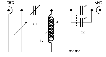
Next try, the
SPC transmatch
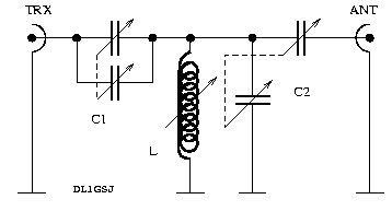
Circuit description
For theoretical background I would like to point the reader to the
common
standart literature as the famous RF textbook of Meincke and Gundlach,
or comparable other readings.
The first approach was thought as an experiment to understand the so
called
ultimate transmatch (UT, first proposed by Lew
McCoy).
In principle I would recommend this design, also driven by my practical
experience. It delivers good matching with moderate bandwidths. Besides
that this design might have a slightly higher loss.
Apart from what I have written in the first version of this text, all
the parts were fine to build a UT-ATU, but the rotary switch, and my
attention
at this time, fooled me. Thinking I got a 1x12 switch, I soldered the
wires
fitting this type. A few days later, reading a catalogue, it was clear,
that the built in think is a 2x6 type. An additional switch cured the
"problem".
So, the finally completed ATU now is an UT.
Advantages: very smooth tuning even at the more critical frequencies
like 29.690MHz, our local (Hamburg, Germany) repeater. QRO in this
design
seems not to be harmful at all, 120W RF on all available bands (40m to
10m) were matched to a 2m wire as well as to a 10m wire w/o sparkling
ATU
;-)
As a comparison, I chose the
series-parallel capacitance
transmatch
(SPC), for the reason that it took me just two leads reconfigured to
convert
on to another. Formerly I also planned to test the
standart
transmatch,
but the overwhelming wish to get on air forced me to stay at the simple
- to - obtain - by - the - most - simple - modification - design
(smiley!).
Disadvantages in this design (agn, have a glance to the textbooks) are
the extreme narrow bandwidths and the low QRO ability (high Q).
What to chose if money plays no role? Certainly I would go for the
UT,
with two two-gang vernier capacitors at 1nF max (in both sections) and
a roller inductor... if... but... it's all built from the junk-box.
Parts descriptions
The
capacitors are the simple part. I just found them on the
bottom
of my junk box. They look like they were intended to go into AM
broadcast
receivers. In either design one has both sections wired in parallel.
The
inductor, the tricky thing in matching units with
variable
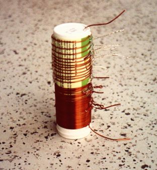
inductance. For the body I found an old pill container with a diameter
of 4cm. The coil is then wound on this with 60 windings of 1mm enameled
copper wire. The first 36 windings tight together, the rest with
increasing
wire to wire distances to the upper (hot) end of the coil. Tabbings are
located at the windings 19, 28, 37, 42, 47, 50, 53, 55, 57, 58 and 59
for
use with a 12 positions rotary switch shortening to ground, as I
thought...
In reality it's a 2x6 with an additional switch.
SWR indicator
My good friend Rico (DF2CK) had
the heart to donate a PCB reflectometer to me. To make one yourself,
have
a look at Harry's (SM0VPO)
Homebrew Page. Can't remember the way Harry did the rest, I added a 47k
potentiometer for sensitivity adjustment, and a 4k7 suppression
resistor
to the forward meter, for reasonable reading during the tuning process.
The meter itself is a standart stereo VU-meter, found in obsolete tape
recorders (other superb parts could be found there likewise).
Usage: Highest sensitivity and lowest reasonable RF power to start
with.
During the tuning you certainly will increase the RF power the closer
you
are to good matching. With CW, your favoured mode ;-), you then
automaticaly
will have the correct sensitivity setting during QSOs. For SSB
contacts,
you should keep in mind to reduce the sensitivity close to zero after
tuning.
The clicking meters will remember you to do so elsewise. Weak nerves
would
make you think of a sparkling capacitor, hi!
Tuning procedure
Yes, I know, that's common knowledge... but... we have two designs in
this
report. My experience was that the both designs have a contrary
behaviour.
Tuning with the UT: Fiddle during RX with all the buttons to get the
loudest noise. You're allready close! Next is done with a little RF
applied,
power depending on the band, little fine tuning, done! QSO! Tuning
mainly
was done during RX. On the other hand I experienced that the RX maximum
must not be the minimum in SWR.
Tuning with the SPC transmatch: More difficult, because of the
narrow
bandwidths. Set your transmitter to a few tens of milliwatts to find a
C-L-C combination where the reflected power is halfways acceptable. Now
the game begins! By slightly in/de-creasing certain capacities and
inductivities
find a good match. You will notice, it's much more complicated to find
a good match, as the SPC transmatch with the given parts will provide
exactly
one for a specific aerial<->QRG combination.
Experiences
Clearly the SPC transmatch easily is able to match a 2m wire to 3.5Mhz
w/o any problem, but, whatever band you're QRV on, watch the reflected
power... Using the SPC transmatch, you will have to retune every tens
of
kHz. The UT give, as mentioned above, broader bandwidths. With both
designs
it now is possible to match a 2m wire to all bands (even 160m, although
this makes no sense at all). It was easy to confirm the statements
given
in the literature about the behaviour of the presented matching
networks.
So, before you start soldering, think about what kind of aerial you
want
to match, and have a closer look to the textbooks. The opinion given
there
is that the UT can better handle inductive loads while the SPC
transmatch
is performing smoother on capacitive loads.
Photographs
The inductor. I know, does not look extremely professional...
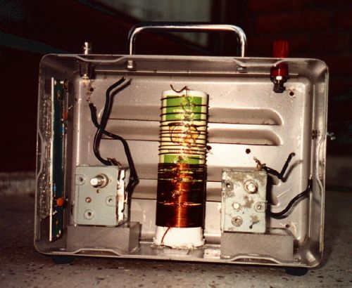
Box, partially assembled. The capacitors are glued to
PVC insulators
(using hotglue). Also the pill container inductor is glued to the box.
On the left side, you can see the reflectometer PCB.
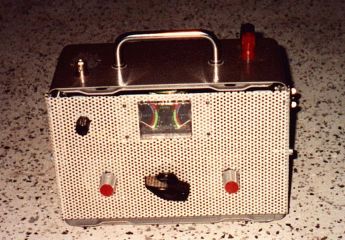
Box, completed. The knobs for the capacitors nowadays are replaced
by larger ones, depending on the settings your hand has a strong
influence
to the capacities.