If all goes according to plans/wishes, Dutch radio amateur will soon be allowed to use the 4m band between 70.0Mhz and 70.5Mhz. Trying to avoid the mistake of being surprised and hence not properly prepared for 600m, I started considering options for 4m.
First thing was looking for available surplus/commercial equipment. Unfortunately, in this range, all available surplus rigs are providing FM only. Best candidate so far, the VRC8000; actually, I plan to pick up one, before they are all gone. Advantage of this rig, it will also cover 6m.
I guess, a lot of operation will make use of CW and USB. Since no commercial rig seems available, a transverter could be the best shot here.
There are two CMOS oscillators available which would be suitable for the job converting/transverting to the 30m band: 60MHz (regular mixing) and 30MHz (subharmonic mixing).
Another two CMOS oscillators would enable us to convert the 4m band to the 6m band: 20MHz (regular mixing) and 10MHz (subharmonic mixing).
For being prepared, I will to pick a VRC8000 asap, and also consider to build a subharmonic transverter for the 6m band.
Monday, December 27, 2010
Tuesday, December 21, 2010
AKAI APW20 World Receiver
A new member to the receiver collection, the AKAI APW20. The device grinned at me in my local entertainment shop and for just 75 Euros... too seductive.
I will spare you most of details that can be found on AKAI's website. Here are just some interesting bits and pieces.
On LW, MW and SW, small tuning steps are 1kHz. For SSB a fine tuning pot is present. When rolling over frequencies, no (stupid) mute function interrupts audio.
LW goes up to 519kHz, covering NAVTEX, which I could directly hear from my living room.
Although the receiver has got a connector for an external SW and/or VHF antenna, the unmodified receiver does not switch to an external aerial for neither LW nor MW.
The rotary encoder not only changes frequency, is also can be used for adjusting volume. There is a line-out jack (grabber) and also a line-in (?). The rig is provided with a mute button, which will mute the loudspeaker and phones but not line-out.
Added bonus: built-in thermometer.
The APW20 may not be the best world receiver in terms of ham-radio, I believe however the APW20, in its intended function, is the best world receiver in my collection. I may even reach out and get a second one tomorrow, one for the boat, one for the suitcase.
Sunday, December 19, 2010
600m QRP TX at the Plumbtenna - VFO Range
Did some additional soldering on the 600m QRP TX, which is now foreseen with a BNC antenna socket. Hooked up the Plumbtenna (matching&coupling details) and just went for it.
The first tests, once again, were done indoors, from the ground floor.

Lots of plasma TV lines. It seems clear that the Plumbtenna actually radiates, at least a little bit. The HF3's AGC is clearly pulled (ant: Octoplumb, 2 stories higher). I did a little keying, nothing of significance though.
The spectrum indicate a VFO range from just below 501kHz to 503.2kHz. Fingers crossed that this will fall into the range (hopefully) to be assigned to radio amateur at the WRC12.
Friday, December 17, 2010
600m QRP TX update
It is about time to hurry up. Just a few more days and my 600m permit will have expired. As my energy slowly seems to be returning (don't ask what drained it - the regular reader may have a clue though), my soldering iron heats up more regularly. Today, the last drips of solder are dropped and the 600m exciter (see earlier post) has been given a "power stage", namely a 74HC240 operated at 8V.
Just applied some power, no keying yet... neither an aerial, just a few centimeters of wire. Still my grabber's AGC was pulled (tx-ing from ground floor through two reinforced concrete ceilings).

The spectrum shows DI2AM at 505180Hz. The signal at 503200Hz (1955z) would be me testing.
The HC240 developed slightly elevated temperature. I guess this is normal when running it at 8V. I said, the signal was not keyed, and it wasn't, however, I was handling the PCB, feeling temperature etc, hence the variation in signal strength.
I hope that, later 2nite, I will have hooked up a QRSS keyer to the transmitter and have it wired up to an aerial (I figure that will be the original Plumbtenna).
Saturday, December 4, 2010
I/Q-SDR Local Oscillator
Just an idea, have not tried it yet... Inspired by YU1LM, I thought of a frequency independent method for creating the I/Q phase shift of 90 degrees.
You may remember my sub-harmonic approach at half the operating frequency. Here a RC network took care about the 45 degrees phase shift. An RC network is ideal for a 45 degrees shift, since R=XC; this was the trick in the sub-harmonic case. However, such an RC network is only accurate in a narrow stretch of frequency.
In YU1LM's designs, a similar RC network is used for oscillators on the operating frequency and on twice the operating frequency.
Twice the operating frequency is a very appealing thing actually. Frequencies are not so terribly high in comparison to the traditional four times the operating frequency method. However, said last mentioned method creates exactly the shift required, due to the purely digital character of the design.
So, why are twice the operating frequency local oscillator so interesting? Very simple, we have QRP crystals for every band. The QRP frequencies are traditionally on the higher end of the CW portion of a band. Divide that such a frequency by 2 will get us about in the middle of the "regular" CW range of the band one octave lower. Examples:
I hope, that I could come up with a pure digital design that will function independently of the frequency it is used at, i.e. no analogue frequency shifting.
Have a look at the concept (there may be details missing in the schematics!):

How is it supposed to work?
U1A (XOR) forms the typical Pierce type crystal oscillator.
U1B is wired as "driver" and is supposed to provide some pulse shaping. Could be that U1B better should be an inverter, meaning, the input which is grounded here, could be wired to 5V.
U1C is an inverter, thereby creating a phase shift of 180 degrees.
U1D is a driver, keeping the original phase. It seems not necessary on the first glance to have this driver, however, it is important to compensate for the delay created in U1C.
U2A (D-type flip flop) and U2B are configured to divide the incoming frequency by 2. Dividing the signal frequencies by 2 means that the 180 degrees phase shift created by U1C and U1D will be just 90 degrees at the frequency divided signals.
Added bonus: I/Q reversal could easily be realized by swapping the roles of U1C and U1D by means of a simple dual toggle switch.
I figure, this design could actually be relatively universal, since Pierce type oscillators are rather forgiving what required passive components is concerned. All the rest is just digital ups and downs, ergh, highs and lows, I wanted to write.
You may remember my sub-harmonic approach at half the operating frequency. Here a RC network took care about the 45 degrees phase shift. An RC network is ideal for a 45 degrees shift, since R=XC; this was the trick in the sub-harmonic case. However, such an RC network is only accurate in a narrow stretch of frequency.
In YU1LM's designs, a similar RC network is used for oscillators on the operating frequency and on twice the operating frequency.
Twice the operating frequency is a very appealing thing actually. Frequencies are not so terribly high in comparison to the traditional four times the operating frequency method. However, said last mentioned method creates exactly the shift required, due to the purely digital character of the design.
So, why are twice the operating frequency local oscillator so interesting? Very simple, we have QRP crystals for every band. The QRP frequencies are traditionally on the higher end of the CW portion of a band. Divide that such a frequency by 2 will get us about in the middle of the "regular" CW range of the band one octave lower. Examples:
- 28.060 / 2 = 14.030
- 14.060 / 2 = 7.030 (here we actually hit the QRP frequency)
- 7.030 / 2 = 3.515
- 7.040 / 2 = 3.520
- 3.686 / 2 = 1.432 (3.686MHz is a cheap standard crystal)
I hope, that I could come up with a pure digital design that will function independently of the frequency it is used at, i.e. no analogue frequency shifting.
Have a look at the concept (there may be details missing in the schematics!):

How is it supposed to work?
U1A (XOR) forms the typical Pierce type crystal oscillator.
U1B is wired as "driver" and is supposed to provide some pulse shaping. Could be that U1B better should be an inverter, meaning, the input which is grounded here, could be wired to 5V.
U1C is an inverter, thereby creating a phase shift of 180 degrees.
U1D is a driver, keeping the original phase. It seems not necessary on the first glance to have this driver, however, it is important to compensate for the delay created in U1C.
U2A (D-type flip flop) and U2B are configured to divide the incoming frequency by 2. Dividing the signal frequencies by 2 means that the 180 degrees phase shift created by U1C and U1D will be just 90 degrees at the frequency divided signals.
Added bonus: I/Q reversal could easily be realized by swapping the roles of U1C and U1D by means of a simple dual toggle switch.
I figure, this design could actually be relatively universal, since Pierce type oscillators are rather forgiving what required passive components is concerned. All the rest is just digital ups and downs, ergh, highs and lows, I wanted to write.
Wednesday, December 1, 2010
NIKKEI NRB10 or a Retro QRP Enclosure
I should not be left alone in electronics stores, I guess. The temptation of buying one of these was just to great, even if the price of about €20 is not really calling bargain.
Here what the receiver looks alike
I figure, the ideal front configuration for a multi-band CW QRP station. Looks cool too! The switch on the right-hand side has got 4 positions: OFF - FM - AM - AUX. Some ideas for that switch:
Nice bit on the kit, the main tuning knob is equipped with a vernier drive!
The red and green LEDs could serve all sorts of purposes... and also the scale back light could be used for something.
What about the back side of the radio? Again, perfect for QRP! Have a look:
First of all, the material of the back cover seems good workable soft plastics. More interestingly however, enough sockets for all sorts of things. Some thoughts:
I can't wait to have that box operable, sitting on my living room table. Hmmm, probably, I should write less and solder more ;-)
Here what the receiver looks alike
 |
| NIKKEI NRB10ZT |
- OFF - 80m - 40m - 20m (multi-band CW transceiver)
- OFF - AM - LSB - CW (75/80m single band multimode transceiver)
- OFF - RX - TX - TUNE (75/80m AM transceiver)
- OFF - 2.7kHz - 1kHz - 500Hz (single band CW-TRX w/ several filters)
Nice bit on the kit, the main tuning knob is equipped with a vernier drive!
The red and green LEDs could serve all sorts of purposes... and also the scale back light could be used for something.
What about the back side of the radio? Again, perfect for QRP! Have a look:
 |
| NRB10 back cover |
First of all, the material of the back cover seems good workable soft plastics. More interestingly however, enough sockets for all sorts of things. Some thoughts:
- keep the RCA for the speaker, since this is already done
- use the mains power cord to connect to the 12V station supply
- replace the 75Ohm socket by a 50Ohm BNC socket
- headphones will remain as is, it is nice to have the correct symbol printed on the cover
- REC OUT also could be used as such, for connecting the rig to a computer
- AUX will serve as a KEY in or a MIC/PTT
I can't wait to have that box operable, sitting on my living room table. Hmmm, probably, I should write less and solder more ;-)
Tuesday, November 30, 2010
SmallWonder Labs PSK-30 QRSS/WSPR mod
In the PSK-30, Dave uses an intermediate frequency of 4.000MHz and a local oscillator employing a 6.144MHz crystal. The oscillator is pulled into place to match the PSK31 center of the 30m band.
In order to get the LO down to our QRSS/WSPR range, one may consider just pulling the oscillator further. However, this possibly compromises stability.
My suggestion here is to pen down a 6.144MHz standard crystal to 6.1387MHz, which is very easily done.
Information about penning down a crystal, you will find here on this blog.
Please not, one needs to make sure that the BFO is set for USB!
SmallWonder Labs PSK-20 QRSS/WSPR mod
Some time ago I built a PSK-20. Even though PSK31 can be fun occasionally,I was thinking of added value to the radio.
The radio uses an intermediate frequency of 9MHz, which is mixed with a 5.0688MHz "computer" crystal oscillator.
I see two possibilities:
Actually, I may start with option #1, to keep the original functionality.
The radio uses an intermediate frequency of 9MHz, which is mixed with a 5.0688MHz "computer" crystal oscillator.
I see two possibilities:
- Make the 5.0688MHz crystal replaceable with a 5.000MHz crystal. This mod will get you to the 20m QRSS band at 14.000800MHz and the radio will still be usable for PSK31.
- There is no WSPR in this mod? Yes, there is, it would be all about penning down a 5.120MHz crystal to 5.0956MHz, which is quite a stretch but doable.
- Some additional frequencies in the upper digi-mode band (14.101-14.112MHz) are reachable in a similar way.
- Finally, there is a 5.200MHz crystal, which would make up to a perfect single channel SSB DXpedition transceiver. I guess one needs to look at the IF-filter response in this one.
- Change the intermediate frequency to 10MHz and the local oscillator to 4.000MHz.
- PSK31 operation will be gone, since there is no (cheap) crystal for 4.070MHz. OK, the last statement is not entirely true, one could pen down a 4.096MHz crystal to 4.069MHz, although, 27kHz is a lot.
- But, WSPR is on the easy side by using a 4.096MHz xtal in the LO.
- Additionally, one SSB channel is available with the LO running at 4.194MHz; I guess one needs to look at the IF-filter response in this one. 14.194MHz would be ideal for SSB DXpeditions.
Actually, I may start with option #1, to keep the original functionality.
Monday, November 29, 2010
Clarifier Calibration Idea
Inexpensive receivers as the HF3 need occasional calibration of the clarifier since such receiver to exhibit some temperature drift. One option is zero-beat a known carrier, another option is adjusting a known carrier to create a beat close to the audio frequency we want to use/listen to, e.g. 2Khz, and display it on a spectrum display.
And here would be my planned approach to the second option. A micro-controller (PIC, PICAXE, ATMEL, etc.) programmed as frequency counter of particular kind. Lets count as precisely as possible around 2kHz.
Here are some ideas how to display the deviation from 2kHz:
The following idea is for the more advanced builder. It should also be seen as a modification to the receiver. The clarifier-potentiometer could be replaced by some circuitry creating/controlling the clarifier varactor. PWM could be an idea here. The concept would be to "visit" a known carrier, activate the counting and adjust the varactor voltage such that the counter counts a 2kHz beat. Now deactivate counting and keep the varactor voltage constant. Actually, in a grabber setup, one may consider to have such "calibration visits" periodically (maybe every 3h) executed by the micro-controller, e.g. by switching between memory channels.
And here would be my planned approach to the second option. A micro-controller (PIC, PICAXE, ATMEL, etc.) programmed as frequency counter of particular kind. Lets count as precisely as possible around 2kHz.
Here are some ideas how to display the deviation from 2kHz:
- 5 LEDs: red (+/-10 to -+/-5Hz), amber (+/-4 to +/-2Hz), green (from -1Hz to +1Hz)
- 7 segment display: deviation in Hz, decimal dot a negative sign indicator
The following idea is for the more advanced builder. It should also be seen as a modification to the receiver. The clarifier-potentiometer could be replaced by some circuitry creating/controlling the clarifier varactor. PWM could be an idea here. The concept would be to "visit" a known carrier, activate the counting and adjust the varactor voltage such that the counter counts a 2kHz beat. Now deactivate counting and keep the varactor voltage constant. Actually, in a grabber setup, one may consider to have such "calibration visits" periodically (maybe every 3h) executed by the micro-controller, e.g. by switching between memory channels.
Tuesday, November 23, 2010
CompuLab Fit-PC2 1.1GHz
It arrived, and I had some time to play with it. Here are some first thoughts.
This PC is damn small! Really!! As everyone else who did a review on this tiny piece of art work, I have to state, the things is smaller that I thought it would be! To stay in QRP standards, the PC is just a fraction bigger than two Altoids tins.
So, here's what my impressions are.
My PC came w/ ubuntu 9.10 ... and that is what it should run, I think. The problem with ubuntu is, it motivates you to update it.... don't do it! Some drivers seem not to be compatible with more recent versions.
Playing with some other operation systems, the following remarks, WinXP works ok with the drivers found on CompuLabs wepage. Win7 worked, however, I got a crash or two, I could however not find out why.
Finally, ubuntu 9.10 came out best and hence will be the OS on my Fit-PC2 (WLAN works too).
A final test concerning the OS will be running Jolicloud on it... I will report about this by updating this posting.
Some words on the hardware. The device does not employ a fan. Even though the case looks like cheap plastics, it actually is made from Al and serves as a heat sink. The device can develop some temperature...
The manufacturer however design the PC for 24/7 up-time, I therefore believe that the temperature is not issue here.
As indicated in the title, I bought the 1.1GHz version. This may have been a mistake, not a big one however. This version is the only one of the Fit-PC2 which wont be able to read miniSDHC-cards. So, 2GB is the limit on SDHC-cards. With a built-in 160GB HDD this is no real issue to me.
QRM: The USB-keyboard/mouse created some rf-noise. I also could hear the attached LCD-screen in the receiver. The switching 12V PSU that came along with the PC created some QRM too. I have not yet figured out how noisy the PC itself is.
Since this is a relatively weak CPU, my impression is that the operation system should be made a light as possible, meaning, all services not required should be disengaged. The usual linux-distro carries a lot of stuff which would not be required on a daily basis, all this could/should be disabled for enhanced system performance.
Should I ever buy one of those PCs again, I would choose a more powerful model, in particular for the added miniSDHC capability, I do however not regret having bought the one I got.
Sunday, November 21, 2010
The Inside of an Indicator Buoy
Sort of off-topic...a signaling buoy on my boat required maintenance... in other words, it was not up to its task anymore, and will be replaced. Those things are supposed to be mounted to a lifesafer, so that it can be found by the MOB (Man Over Bord), and further, that the MOB can be found by the crew of sailors.
Now, let's have a peak what is inside....

The orange body of the buoy is closed by a transparent cap, sealed by a black rubber gasket. The inner life of the buoy consists of a PCV tube which holds (from left to right) some Fe-ballast, an opening for loading 4 D-type batteries, a spring for those batteries, a PCB w/ a flasher circuit, an Hg-switch and a mount for the bulb.
I leave it to your imagination what to do w/ this info... The only thing I can say is, if you find any flaw in your safety gear, discard w/o hesitation, lives will depend on the stuff! You don't want to have an indicator buoy not flashing properly if yours friends live in on the line.
Look after your safety gear, respect expiry dates and replace on time!
Allzeit eine handbreit Wasser unter'm Kiel!
Wednesday, November 17, 2010
HYmini - a QRPp Wind Generator
Steve G0XAR brought up a "Wind Generator", which could be useful for powering an MEPT. Guess what, I could not resist and bought one.
This is what I got for just £9.95:

What you see is, the wind generator, a USB-cable and a set of adapters to connect a device to be charged. Interestingly there is a 5V PSU supplied, which, at first sight seems not to make any sense.
However, the device is called "portable power bank" and actually carries an internal 1200mAh accumulator. Meaning it is supposed to be carried about for charging up other gadgets with 5V supply voltage. As preparation for outdoor activity, the internal accumulator could therefore be charged from mains supply.
Surprisingly, the optional bike mounting bracket was included in the package! Many thanks to "ecohamster"!
Very unfortunately, the device is not weather proof. The manual reads that the wind generator must not be used under wet conditions. That is, I believe, a huger downer!
This is what I got for just £9.95:
What you see is, the wind generator, a USB-cable and a set of adapters to connect a device to be charged. Interestingly there is a 5V PSU supplied, which, at first sight seems not to make any sense.
However, the device is called "portable power bank" and actually carries an internal 1200mAh accumulator. Meaning it is supposed to be carried about for charging up other gadgets with 5V supply voltage. As preparation for outdoor activity, the internal accumulator could therefore be charged from mains supply.
Surprisingly, the optional bike mounting bracket was included in the package! Many thanks to "ecohamster"!
Very unfortunately, the device is not weather proof. The manual reads that the wind generator must not be used under wet conditions. That is, I believe, a huger downer!
Wednesday, November 10, 2010
The HC-8 CW QRP Transceiver
I got something on my mind, which is probably not too hard to design, and could be a nice trx to take along on journeys: a modern days clone of the HW-8.
The design will entirely be based on 74HC digital electronics, hence the name HC-8.
It will employ a 8.867MHz super-VXO. Reason for this being the HW-8 itself (find out more about this in an earlier post).
The CW portions of 160, 80, 40, 20 and 17 can easily be covered by such a super-VXO in combination with some cheap crystals. 30 required some more efforts. For good measures, I will include the already shown list:
As mentioned above, the plan is to use digital gates as much a possible.
This would be possible solutions:
Practical Considerations
With the 74HC240 running from 8V (upper limit for this particular chip) one could imagine to drive a class-E switch-mode PA (IRF510) that easily would produce 5W RF.
The HC-8 wont be providing any IF filtering. I intend to go for pure direct conversion, (super) VXO on 8.867Mc and r.i.t. on the respective other oscillators. I have not yet figured out how to do this the best
way.
Switching low pass filters in a multi-band transceiver can pose a problem, therefore I am envisaging to go for 2 bands only (switches are available, small and not too expensive), but build two rigs:
Added Value
You're missing 30m? OK, here is 30m, it's a tricky one however, in particular for filtering! Frequency division would be available using 74HC74 Flip-Flops. Signal source: a 5.0MHz xtal or a not so common 38.0MHz oscillator.
Even long-wave would would be available (although such a rig would maybe not that practical for such low frequencies):
Note: For some bands the VXO is required to oscillate above 8.867MHz. Some thought should be invested when designing the VXO. Maybe for the reason of frequency coverage, the VXO should involve discrete transistors in place of digital gates.
As antenna to go along with the rig I see the RockLoop as best fitting. Very narrow-band antennae have the advantage of good harmonics suppression. Alternatively a high-Q transmatch should be used for the same reason.
The design will entirely be based on 74HC digital electronics, hence the name HC-8.
It will employ a 8.867MHz super-VXO. Reason for this being the HW-8 itself (find out more about this in an earlier post).
The CW portions of 160, 80, 40, 20 and 17 can easily be covered by such a super-VXO in combination with some cheap crystals. 30 required some more efforts. For good measures, I will include the already shown list:
- 160m: 8.867 - 7.000 = 1.867
- 80m: 8.867 - 12.406 = (-) 3.539
- 40m: 8.867 - 1.843 = 7.024
- 20m: 8.867 + 5.185 = 14.052
- 17m: 8.867 + 9.216 = 18.083
As mentioned above, the plan is to use digital gates as much a possible.
This would be possible solutions:
- 74HC00 - oscillators, drivers, AF-amp
- 74HC04 - oscillators, drivers, AF-amp
- 74HC86 - oscillators, drivers, mixers
- 74HC4066 - oscillators, mixers, signal routing, class E "driver"
- 74HC240 - driver, PA, AF-amp
Practical Considerations
With the 74HC240 running from 8V (upper limit for this particular chip) one could imagine to drive a class-E switch-mode PA (IRF510) that easily would produce 5W RF.
The HC-8 wont be providing any IF filtering. I intend to go for pure direct conversion, (super) VXO on 8.867Mc and r.i.t. on the respective other oscillators. I have not yet figured out how to do this the best
way.
Switching low pass filters in a multi-band transceiver can pose a problem, therefore I am envisaging to go for 2 bands only (switches are available, small and not too expensive), but build two rigs:
- 80/40 for NVIS
- 20/17 for DX
Added Value
You're missing 30m? OK, here is 30m, it's a tricky one however, in particular for filtering! Frequency division would be available using 74HC74 Flip-Flops. Signal source: a 5.0MHz xtal or a not so common 38.0MHz oscillator.
- 8.867 + (5.000/4) = 8.867 + 1.25 = 10.117
- 8.867 - (38.000/2) = 8.867 - 19.000 = (-) 10.133
Even long-wave would would be available (although such a rig would maybe not that practical for such low frequencies):
- 8.867 - 9.000 = (-) 0.133
Note: For some bands the VXO is required to oscillate above 8.867MHz. Some thought should be invested when designing the VXO. Maybe for the reason of frequency coverage, the VXO should involve discrete transistors in place of digital gates.
As antenna to go along with the rig I see the RockLoop as best fitting. Very narrow-band antennae have the advantage of good harmonics suppression. Alternatively a high-Q transmatch should be used for the same reason.
Monday, November 8, 2010
HB-1A now Ten-Tec R4030 & R4020
Interesting... the HB-1A QRP-transceiver, made by BD4RG, which disappeared from ebay where it was sold for a while reappeared at Ten-Tec's product range as R4030 and R4020. The manual, download-able from Ten-Tec, even shows "HB-1A 3 Band CW QRP Transceiver".
Funny, the original 3 band TRX is now available as 2 different 2 band TRXs. I wonder why this limitation, which most likely is just a bit of code in the main controller, was added. In particular since the DDS still is mentioned to deliver a receive range from 5-16MHz, as in the original HB-1A. Looking at the schematics, the only reason that I can see is the switchable low-pass filter. Probably some FCC requirements about spurious transmissions. I have doubts about commercial reasons; who would by two transceivers being more or less the same. When going on a trip, the three bands 40, 30 and 20 seem ideal. Now the OM has to select, either the band that is open around the clock, or the band that delivers the best dx results in average.
For myself, if I would consider trying to get my hand on a radio like this, I would go for the original HB-1A. Harmonics suppression in my travel kit is done by the aerial, which usually is a very narrow-band "rockloop".
When it all comes to buying, I would very likely go for the real original, the Elecraft KX1, which nowadays covers all band from 80 to 20.
UPDATE: Today, 10.11.2010, I decided to order a Hendricks PFR-3 kit. The design is thought through and straight forward. The controller however allows only for 40, 30 or 20m HAM-band action, no BC-RX though. In my view, this is a tiny downer...
The PFR-3 transceiver carries a built-in manual transmatch and a preselector, which sounds "old skool"... and it is! And that is why I ordered the kit.
Saturday, November 6, 2010
SW+ Transceivers for QRSS
I was shopping for QRSS kits once again. And, once again at K1SWL.
The RockMites work great for QRSS, however, this time it was the SW+ Series Transceivers.
The SW+ design employs a three pole crystal ladder filter and a VFO tuned by a varicap.
Lets look at the different models and what would get us to a QRSS range.
SW+ 80
This model uses a 8.000MHz intermediate frequency. Subtractive mixing with a 4.500MHz crystal (standard but maybe harder to find) gets us to 3.500MHz.
The color-burst range is reached by subtractive mixing with a 4.433618MHz crystal. The result will be 3.566382MHz, somewhat low, however, the 4.433618MHz xtal can easily penned down to 4.420MHz. Mixing would then result in 3.580MHz.
SW+ 40
This model uses a 4.000MHz intermediate frequency.
Additive mixing with a 3.000MHz crystal gets us to 7.000MHz.
Subtractive mixing with a 11.000MHz crystal gets us to 7.000MHz.
Subtractive mixing with a 11.059MHz crystal gets us to the novice range 7.0599MHz.
With the help of crystal-penning, the novice range is reachable by additive mixing with a 3.072MHz standard xtal results in 7.072MHz, with some penning 7.0599MHz should not be any problem.
SW+ 30
This model uses a 7.68MHz intermediate frequency. I can't think of any cheap crystal to match up with that frequency. However, there is help!
The 7.68MHz i.f. could be changed to 6.144MHz. From here on, with penning again, additive mixing with a 4.000MHz xtal-oscillator will result in 10.140MHz.
SW+ 20
This model uses a 9.000MHz intermediate frequency. Additive mixing with a 5.000MHz crystal gets us to 14.000MHz
Non-qrss bonus mod: 5.0688MHz super-VXO for regular QRP work.
Further option: use a 10.000MHz intermediate frequency. With a 4.000MHz oscillator we arrive at 14.000MHz. An (additional) alternative 4.096MHz XTAL will result in the vicinity of 20m WSPR.
A 80m QRP-XTAL will result in 22m hifer gear at 13.560MHz.
Possible Mods
The first option keeps the original function, that's nice! Secondly, since the 4.500MHz crystal may be hard to get, one may consider using a 9.000MHz oscillator, based on a 27MHz standard crystal, and divide the frequency by two before, as to obtain 4.500MHz.
The second option renders all VFO parts essentially obsolete. However, the VFO is realized by means of a varicap, which could be used to pull the crystal for coarse frequency adjustment.
FSK modulation can easily be generated with the help if some sort of diode pulling the TX converter's XTAL in the usual fashion.
Audio for the sound-card could be tabbed off just at the AF final's input, just behind the muting transistor.
Due to the 100% duty cycle of FSK-QRSS, the TX output should be reduced.
Conclusions
The RockMites work great for QRSS, however, this time it was the SW+ Series Transceivers.
The SW+ design employs a three pole crystal ladder filter and a VFO tuned by a varicap.
Lets look at the different models and what would get us to a QRSS range.
SW+ 80
This model uses a 8.000MHz intermediate frequency. Subtractive mixing with a 4.500MHz crystal (standard but maybe harder to find) gets us to 3.500MHz.
The color-burst range is reached by subtractive mixing with a 4.433618MHz crystal. The result will be 3.566382MHz, somewhat low, however, the 4.433618MHz xtal can easily penned down to 4.420MHz. Mixing would then result in 3.580MHz.
SW+ 40
This model uses a 4.000MHz intermediate frequency.
Additive mixing with a 3.000MHz crystal gets us to 7.000MHz.
Subtractive mixing with a 11.000MHz crystal gets us to 7.000MHz.
Subtractive mixing with a 11.059MHz crystal gets us to the novice range 7.0599MHz.
With the help of crystal-penning, the novice range is reachable by additive mixing with a 3.072MHz standard xtal results in 7.072MHz, with some penning 7.0599MHz should not be any problem.
SW+ 30
This model uses a 7.68MHz intermediate frequency. I can't think of any cheap crystal to match up with that frequency. However, there is help!
The 7.68MHz i.f. could be changed to 6.144MHz. From here on, with penning again, additive mixing with a 4.000MHz xtal-oscillator will result in 10.140MHz.
SW+ 20
This model uses a 9.000MHz intermediate frequency. Additive mixing with a 5.000MHz crystal gets us to 14.000MHz
Non-qrss bonus mod: 5.0688MHz super-VXO for regular QRP work.
Further option: use a 10.000MHz intermediate frequency. With a 4.000MHz oscillator we arrive at 14.000MHz. An (additional) alternative 4.096MHz XTAL will result in the vicinity of 20m WSPR.
A 80m QRP-XTAL will result in 22m hifer gear at 13.560MHz.
Possible Mods
- Preserve the original QRP-TRX: toggle between the LC-VFO and an external XO.
- QRSSify the TRX: replace the VFO's RC-network by the crystal.
The first option keeps the original function, that's nice! Secondly, since the 4.500MHz crystal may be hard to get, one may consider using a 9.000MHz oscillator, based on a 27MHz standard crystal, and divide the frequency by two before, as to obtain 4.500MHz.
The second option renders all VFO parts essentially obsolete. However, the VFO is realized by means of a varicap, which could be used to pull the crystal for coarse frequency adjustment.
FSK modulation can easily be generated with the help if some sort of diode pulling the TX converter's XTAL in the usual fashion.
Audio for the sound-card could be tabbed off just at the AF final's input, just behind the muting transistor.
Due to the 100% duty cycle of FSK-QRSS, the TX output should be reduced.
Conclusions
- SW+ 80: subtractive mixing cancels temperature drift partially
- SW+ 40: best choice: subtractive mixing 11.000 & 11.059MHz
- SW+ 30: there is a better kit for 30m: the PSK-30
- SW+ 20: the 10MHz i.f. mod will offer the most
Monday, November 1, 2010
136kHz Crystal Pair
Lately, I mentioned a local electronics shop, I guess they would also ship outside the Netherlands. As noted in the previous entry, they have some uncommon crystals in the assortment.
The specific one I would like to focus on today will enable 136kHz action, either by mixing with another crystal, or as superhet design with a couple of options.
Here we go, have a look at 4233.6kHz.... mix it with 4096kHz will get us to 8329.6kHz aaahhh... hmmm.... and:
137.6kHz
According to the band-plan, this is spot on for the lower edge of the QRSS section! Since at about 4MHz crystals can easily be pulled a couple of kHz, the whole band is easily covered.
You already guessed, we will have some options for superhet design too. I would recommend the filter being made from 4096kHz crystals, reason being the better availability. Additionally, the 4096kHz intermediate frequency allows for a 2048kHz subharmonic BFO.
Saturday, October 30, 2010
MFJ-1621 Portable Antenna
Got myself some additional gear to play with, an MFJ-1621 portable antenna. It was just too tempting...
Well, I don't expect any miracles, in particular with the mixed reviews found on the internet.
The thing I am curious about in particular, will it be any good for QRSS. Regarding Peter's (DL6NL) great success using a so called MicroVert antenna, I am not expecting a total failure.
Both antennae have a couple of design features in common, a very short radiator, some L/C stuff and a long coaxial feed-line.
The 1621's matching box is said to be good from the 40m band up to the 10m band. Some OM claim the antenna could also be used for 6m and 2m.
I figure, here is where some experimentation could come in. It would be nice to also cover the 80m band, at least partly. The telescopic whip attaches with a 3/8 inch thread also found on CB-antennae. And this could be a start, just use one of those 27MHz whips and see what happens. Additional load inductors the respective threads would be thinkable.
Update (late hours)
Alarmed by some postings (about connections not being soldered), I felt urged to open the tuning box and have a peak. Check it out:
Well, I don't expect any miracles, in particular with the mixed reviews found on the internet.
 |
| The MFJ-1621 portable antenna system |
Both antennae have a couple of design features in common, a very short radiator, some L/C stuff and a long coaxial feed-line.
The 1621's matching box is said to be good from the 40m band up to the 10m band. Some OM claim the antenna could also be used for 6m and 2m.
I figure, here is where some experimentation could come in. It would be nice to also cover the 80m band, at least partly. The telescopic whip attaches with a 3/8 inch thread also found on CB-antennae. And this could be a start, just use one of those 27MHz whips and see what happens. Additional load inductors the respective threads would be thinkable.
Update (late hours)
Alarmed by some postings (about connections not being soldered), I felt urged to open the tuning box and have a peak. Check it out:
 |
| MFJ-1621 tuning box, original state |
Well, all connections are soldered, that's good. However, have a look at the flimsy wire gauges used.... When operating on the lower bands, I am expecting a lot of current going through the inductor, returning to the coax-shield via the orange ground-return wire passing by the meter.
Hence, there is a mod I performed before I even tested the new toy... That is a first actually... have a look:
 |
| MFJ-1621 tuning box, first mod |
The flimsy orange ground-return wire is replaced by (brown) solid copper mains installation wire. Additionally, I choose to substitute the (flimsy) white whip connector wire by the same stuff. Depending on the performance of this setup, I will (very likely) replace the other r.f. carrying wires with heavier gauges...
As a next mod, I consider to add a coax-connector for the feed-line. I would rather transport three parts (whip/tuner/cable) than just two wherein some cable dangles from the tuner box.
Update (31.10.2010)
Some more findings...
All connection required were soldered, but... still some two fabrication errors to correct. The first mistake was done with the wiring of the band switch, here, the leads to the positions for 18MHz and 24MHz were confused and hence tabbed the coil in the wrong positions.
 |
| band switch in the original state |
What is to be seen in this photograph? I would like to draw the attention to the tabs shown in the red circle. The green lead tabs the coil for the 18MHz band, the blue-white lead connects the coil to the 24MHz position. In this setup, the 24MHz band would get more inductance than 21Mhz, that does not make any sense, therefore, it only could be a manufacturing mistake.
Have a look at the corrected version.
 |
| corrected wiring |
Here you can see the corrected wiring, simple exchange of the tabs. I did that soldering with my regular soldering station which was a little weak for all the amount of metal to warm up, the result, not a nice vista, but it works...
I mentioned two manufacturing glitches... that was the first one, the second one was the wrong alignment of the band switch knob. OK, that fix was an easy one!
Conclusion of the bug-fixes: I understand now why some reviews point towards absolute uselessness of the MFJ-1621. My model in the hands of a newcomer would have resulted in a heap of frustration!
Here is a further observation. To understand the following point I am trying to make, some note should be added to the function of the band-switch. This switch shortens tabs if the coil to ground, therefore the full coil will be used for the lowest 40m band position. And now, please have a look at the photo shown below.
 |
| band selector switch |
I indicated the positions of the respective bands as they are marked on the front plate. You can see 4 positions marked for the 40m band. Actually, only three of the 7MHz positions differ. The one position I labeled 7* is not connected to anything. The 7MHz position next to it, however, is connected to the cold end of the coil and is the common pole of the band switch. Therefore, the switch always shorts the different terminals to the "second" 7MHz position, hence it also shorts the 7* position to it... Well, that does not make a lot of sense. But ok, it does not do any harm either. There may be a use for this terminal, however, I am presently too lazy to think of one.
On air tests: just some short tests. Using the FT817 in its lowest power setting, I could resonate the antenna to all bands. I have to admit that, contrary to the teachings of the user's manual, I did not unroll the coax cable. With the corrected band-switch position, the bands 40m to 17m were spot on. Nothing to complain about. However, for 21MHz and above, it seems advisable to use the antenna set to the next lower band, which will result in a much sharper SWR dip, indicating higher Q, which would help in a resonant antenna. The built-in field-strength meter was slightly deflected even with the transmitter's power settings at the minimum.
With a contest going on, I could hear signals on essentially every band, the reception of the MFJ-1621 is surprisingly good. A clone of such an antenna could possibly be an interesting alternative, also for QRSS-grabbers.
Thursday, October 28, 2010
The Blibber
Triggered by the comment Guido wrote in the KnightsQRSS-blog and with some experience in QSK-QRSS (see my ealier blabla on the QRSS-ified RockMite) combined with Colin's broad-A1A-QRSS the following idea evolved.
What about a "fast QSK", some would call it TDM, switching between RX and TX constantly in a comparably short period. What about going TX for 1/3sec and RX for 2/3sec. Obviously, some SNR will be lost for the RX and the average transmitted power will be just 30%. Additionally, the transmitted power would create sidesband, which, in this particular case, may even be wanted in order to add signature to the signal. In a regular receiver one would simply hear "blibb blibb blibb".
Speed: Since there will be only one blibb created per second, there would be a reason to slow down the message. QRSS10 would probably be the fastest one could go. I calculated that my relatively long ident (not full call!) would take about 6min 30sec. That would nicely fit into a 10min frame for averaging.
Averaging, speaking of it, could help for the receiving too. The trick could be to divide the 1sec period into three slots, in which two are reserved for receiving. Now, instead of transmitting constantly in one slot, the TX-slot could glide for every 10min cycle. Averaging the received spectra of three cycles would display the full 10min cycle.
Downside: I believe that not only the TXed signal will get some side-bands to it, but also the received signal will suffer from the same. However, it may be desirable to have those side-bands transmitted, for reception, those side-bands could render the spectra really messy.
For sure, there always will be the option of slowing the whole thing down to some WSPR-ish period, avoiding the side-bands.
Monday, October 25, 2010
20m & 40m Dual Band Digimode-TRX
The 2048kHz crystal appearently got some potential, more than I initially thought.
In my previous entry, I motivated digimode superhets for 40m and 20m. The 40m version would be build around a 5.000MHz filter, for the 20m version, a 10MHz filter will do the trick. As you may recall, the idea for 20m was to use a subharmonic mixer, as to have an effective local oscillator frequency of 4096kHz. Well, the same could be done for the BFO. The 40m version already employs a 5MHz BFO, which could be easily used for the 20m version, provided the product-detector is subharmonic too.
And here is the idea for the RX part:
- one switchable front-end
- one (super-)VXO for 2048kHz, maybe using an additional penned down one, lets say for 2035kHz
- one BFO for 5000kHz, slightly pullable, as usual
- two mixers, one for regular mixing, one for subharmonic mixing
- two IF circuits having crystal (ladder) filters, one for 5.000MHz, one for 10.000MHz
- two product-detectors, one for regular mixing, one for subharmonic mixing
- one audio stage
- one input audio stage
- two modulators, one for regular mixing, one for subharmonic mixing
- two IF circuits having crystal (ladder) filters, one for 5.000MHz, one for 10.000MHz
- two converter mixers, one for regular mixing, one for subharmonic mixing
- one switchable linear amplifier
Sunday, October 24, 2010
2048kHz XTAL
Haven't got the luck to obtain any of the before mentioned 2030kHz crystals? Well, there is hope ;-)
What about the 2048kHz standard crystal? This one should be widely available.
Let's see what we can do with this one. First of all, such crystals can be penned down, 18kHz should be doable. But what more can we do?
600m I/Q-SDR
For the typical SDR, one could simply feed this signal into two Flip Flops, resulting in an SDR LO of 512kHz. With a minimum sampling rate of 24kbps, a range from 500kHz to 524kHz would be covered. This is in particular interesting since 518kHz, the international NAVTEX frequency falls into this range.
2200m I/Q-SDR
Taking one of the two 512kHz signal and feed it into two further Flip Flops would provide an SDR-LO of 128kHz, which would provide a frequency range of 116kHz to 140kHz, covering the 136kHz amateur radio band.
40m Digi-Mode Superhet
As non SDR use of the crystal, a more classical approach is in reach: a 2048kHz (super-)VXO and a 5000kHz crystal filter coincides nicely with the 40m digital mode range. The 2048kHz crystal could additionally penned down (see earlier post about xtal-penning) to cover the 40m WSPR and PSK frequencies.
20m Digi-Mode Superhet
In the 20m band, the WSPR frequency is easily covered. The trick here, a 2048kHz (super-)VXO as LO for a subharmonic mixer, which per se doubles the LO-frequency. Hence, the effective LO-frequency would be 4096kHz. In such a concept, it would be somewhat obvious to use a 10MHz crystal filter.
10m CW Superhet
Similar to the 20m concept, a subharmonic mixer would be required. As intermediate frequency, 24.000MHz would be obvious. However, watch out for the correct crystals for the filter! Most crystal will be overtone crystals, for a cheap filter we would need fundamental frequency crystals, and yes, they do exist for 24.000MHz.
40m LSB Superhet
Here is a simple one. The sum of 2048kHz and 5068.8kHz results in 7116.8kHz. I would propose to build a full-lattice filter with two original and two penned down 2030kHz crystals. As LO a super-VXO using 5068.8kHz crystals would an obvious choice. Additional options would be a 5120kHz VXO (getting us to 7168kHz), a 9216kHz VXO (9216-2048=7168), or, for some of us, a 5200kHz VXO (7248kHz).
80m LSB Superhet
This could be a tricky one. I would, once again, propose to build a full-lattice filter with two original and two penned down 2030kHz crystals. A conceivable could employ a 5.74MHz ceramic resonator. Subtractive mixing would provide a range, depending how far one pulls the VFO, of a couple of 10kHz about 3692kHz.
4096er Grabber Receiver
You may remember that my 30m grabber receiver employs a subharmonic mixer. Well, the exact same can be done for the 4096er hf-beacons. However, those beacons spread a little bit more than the 100Hz wide 30m QRSS segment, therefore, I would skip the crystal filter. This would have the advantage of also showing beacons below the 4.096MHz nominal frequency in a good old fashion DSB way.
4096er I/Q-SDR Grabber Receiver
One of the most popular entries on this blog is concerned a subharmonic I/Q-SDR in which the 90 degree I/Q phase-shift is done on half the frequency and hence amounts to 45 degrees on the subharmonic local oscillator. The exact same could be done for the 4096er beacon range (click here for more info) using a 2.048MHz crystal and some RC/RR network as shown in the subharmonic SDR article.
There may be more uses of this crystal, feel free to add comments with additional ideas!
2030kHz XTAL
Browsing one of the regional electronic (online) shops, I found a 2030kHz crystal, which would be perfect for a couple of projects. The order seems a little odd, however, the order reflects the difficulty of the different projects, the further down, the more difficult to realize.
600m I/Q-SDR
For the typical SDR, one could simply feed this signal into two Flip Flops, resulting in an SDR LO of 507.5kHz.
With a minimum sampling rate of 24kbps, a range from 495.5kHz to 519.5kHz would be covered. This is in particular interesting since 518kHz, the international NAVTEX frequency falls into this range.
2200m I/Q-SDR
Taking one of the two 507.5kHz signal and feed it into two further Flip Flops would provide an SDR-LO of 126.875kHz, which would provide a frequency range of 114.875kHz to 138.875kHz, covering the 136kHz amateur radio band.
40m QRP Superhet
As non SDR use of the crystal, a more classical approach is in reach: a 2030kHz (super-)VXO and a 5000kHz crystal filter coincides nicely with the 40m QRP frequency. The 2030kHz crystal could additionally penned down (see earlier post about xtal-penning) to cover lower frequencies in the 40m CW section.
20m QRP Superhet
Also the 20m QRP frequency is easily covered. The trick here, a 2030kHz (super-)VXO as LO for a subharmonic mixer, which per se doubles the LO-frequency. Hence, the effective LO-frequency would be 4060kHz. In such a concept, it would be somewhat obvious to use a 10MHz crystal filter.
10m QRP Superhet
Similar to the 20m concept, a subharmonic mixer would be required. As intermediate frequency, 24.000MHz would be obvious. However, watch out for the correct crystals for the filter! Most crystal will be overtone crystals, for a cheap filter we would need fundamental frequency crystals, and yes, they do exist for 24.000MHz.
40m LSB Superhet
Here is a simple one. The sum of 2030kHz and 5068.8kHz results in 7098.8kHz. I would propose to build a full-lattice filter with two original and two penned down 2030kHz crystals. As LO a super-VXO using 5068.8kHz crystals would an obvious choice. Additional options would be a 5120kHz VXO (getting us to 7150kHz), a 9216kHz VXO (9216-2030=7186), or, for some of us, a 5200kHz VXO (7230kHz).
80m LSB Superhet
This could be a tricky one. I would, once again, propose to build a full-lattice filter with two original and two penned down 2030kHz crystals. A conceivable could employ a 5.74MHz ceramic resonator. Subtractive mixing would provide a range, depending how far one pulls the VFO, of a couple of 10kHz about 3710kHz.
There may be more uses of this crystal, feel free to add comments with additional ideas!
Tuesday, October 19, 2010
The Broompole
You may have seen the previous post, the proposal of faking a Trans World Antenna. Mechanically such a clone would be a challenge, in particular getting good conductivity over the hinges. Maybe I will take on that challenge some other time.
However, what about back to the idea of using the broomsticks for a loaded shortened dipole. But, how get hold the stuff together? BTW, those broomsticks are 1.3m long and have a diameter of 22mm.
This is what I came up with, when searching the hardware store for a solution. The handle snug fits into a 32mm PVC plumbing bit, as shown below.

The idea is now to connect two of those bit by some pipe, such to create space for mounting means and the loading box. Oh, I forgot, I intend to build a center loading box, similar to the one in the Trans World Antennae. OK, back to what I was saying, you can see that the handles of the sticks are equipped with an eye. This comes along quite handy, since the eye more or less aligns with the T-piece's third port. The plan is to rope both broomsticks together which would enable a solid but still easily collapsible setup.
Note, those sticks could be just ideal for a 6m dipole.
Remains to put it all together....
The Broomtenna
The local hardware store offers broomsticks made of aluminum for a price of next to nothing. Some months ago, I picked two of those up, the plan was to build a loaded dipole of sort... I never really got to use them for anything interesting yet, until today, an idea came along.
This could be a blue-print for things to come:
http://transworldantennas.com/
Looking a the TW-antennae, this is what I can see: a centre loaded short vertical dipole with end-capacitors. The company offers manuals for download, I could not resist doing so ;-) The only difference between the various models seems the centre loading box, the mechanical structure appears common to all models.
And here the broomstick come into the game. I figure, a similar structure can be build using 6 of those above mentioned aluminum broomsticks. Electrical insulation, like for the centre piece of the connection to a stand, can easily be done using PVC-plumbing parts.
For ease of manufacturing, I would probably go for a modular setup inside the loading box, meaning, exchangable sets of coils for different frequencies. The box holding the loading network will therefore be picket slightly oversized with a skrew-on lid. I recall to have seen boxed for outdoor electrical installations having such properties.
Not sure when to start with this project, I will however post pictures, as soon as there is something to show.
Thursday, October 14, 2010
New Type of OTHR?
Today, for the first time ever, I see this sort of signal in 30m-spectrum-grabbers worldwide.


To me, this looks like some sort of OTHR, I may be wrong here... Anyone an idea?
Tuesday, October 5, 2010
Rhombic DCTL
Winter and storms arriving, it was time to do something about the wobbly design of the grabber's antenna.
Having had very good results with PE plumbing parts for my weather proof 600m frame antenna, I went to the hardware store today to buy some other material.
Contrary to the 600m stuff, which uses very heavy speaker cable, the DCTL uses lightweight TV twin line and only turn of it. This allows for flimsy 5/8" PE electrical installation tubing. Have a look at the b.o.m.:

My DCTL is 327cm long. An elbow is good for 8.5cm. In order to compensate for the shorter path through the terminal box, the two tubes connected to said box are 2cm longer than the other two.
Consequently, I cut two tubes to the length of 73cm and two to the length of 75cm.
Since today, 1903z, the DCTL is back online, in "tip up" rhombic configuration.
BTW, another reason for selecting this configuration was the wish to lift up the aerial by means of a pole, to improve ground clearance.
 Note, the tubes are held together by Duck-Tape. Plumbing glue could be used, I guess, however, tape does not create such a stink ;-)
Having had very good results with PE plumbing parts for my weather proof 600m frame antenna, I went to the hardware store today to buy some other material.
Contrary to the 600m stuff, which uses very heavy speaker cable, the DCTL uses lightweight TV twin line and only turn of it. This allows for flimsy 5/8" PE electrical installation tubing. Have a look at the b.o.m.:

My DCTL is 327cm long. An elbow is good for 8.5cm. In order to compensate for the shorter path through the terminal box, the two tubes connected to said box are 2cm longer than the other two.
Consequently, I cut two tubes to the length of 73cm and two to the length of 75cm.
Since today, 1903z, the DCTL is back online, in "tip up" rhombic configuration.
BTW, another reason for selecting this configuration was the wish to lift up the aerial by means of a pole, to improve ground clearance.

Monday, October 4, 2010
WSPR 2.1 - a possible solution for 600m
Background
Joe, K1JT, recently made WSPR 2.1 available which now employs I/Q-SDR. Primarily it seems to be intended for the SoftRock RXTX Ensemble.
I figure, with the correct tweek, it could be made to operate on the 600m-WSPR range as well. Not sure about the precise working of the I/Q-SDR option of Joe's software, so 2 scenarios are possible:
Oscillator
In case 1, a SDR center frequency of 500kHz would be just fine, hence, the transceiver design could be based on a simple 2.000MHz CMOS oscillator.
In case 2, the SDR center frequency would need to be 502.4kHz. This would chance the design in so far, that a XO would have to be pulled to 2.0096Mhz. A pull by 9.6kHz could be ambitious on 2MHz, even in a Pierce oscillator, but certainly worth a try.
Mixers
Keep it simple, I would very likely opt for 4066 switches. Other stuff imaginable....
Power Amplifier
We are digital, using carriers, linearity is not the primary goal at this stage. So, simple/cheap possibilities would be IRF510, IRF820 etc.
Thoughts
Frequencies are kinda low, so, this all could be done in pure CMOS, which would have the advantage of a) being low power and b) easily creating 8V output to drive the MOSFET.
I hope I can realize this before the expiry of the experimental license.
Joe, K1JT, recently made WSPR 2.1 available which now employs I/Q-SDR. Primarily it seems to be intended for the SoftRock RXTX Ensemble.
I figure, with the correct tweek, it could be made to operate on the 600m-WSPR range as well. Not sure about the precise working of the I/Q-SDR option of Joe's software, so 2 scenarios are possible:
- An ideal case would be that the software employs its own SDR-LO, meaning that it would be sufficient to have the WSPR-band within the coverage of the SDR-receiver.
- Could be that the software does not provide a "virtual local oscillator". In this case, the SDR-center frequency would need to coincide with the "dial frequency" for the respective band.
Oscillator
In case 1, a SDR center frequency of 500kHz would be just fine, hence, the transceiver design could be based on a simple 2.000MHz CMOS oscillator.
In case 2, the SDR center frequency would need to be 502.4kHz. This would chance the design in so far, that a XO would have to be pulled to 2.0096Mhz. A pull by 9.6kHz could be ambitious on 2MHz, even in a Pierce oscillator, but certainly worth a try.
Mixers
Keep it simple, I would very likely opt for 4066 switches. Other stuff imaginable....
Power Amplifier
We are digital, using carriers, linearity is not the primary goal at this stage. So, simple/cheap possibilities would be IRF510, IRF820 etc.
Thoughts
Frequencies are kinda low, so, this all could be done in pure CMOS, which would have the advantage of a) being low power and b) easily creating 8V output to drive the MOSFET.
I hope I can realize this before the expiry of the experimental license.
Sunday, October 3, 2010
Keying by Counter
Here's another trick I used in one of my rigs, chirp-free keying by means of a counter.
In previous entries, it was indicated that counters could be used to reach a certain frequency, in particular in the LF and MF bands.
Here's an example, well, this example actually reflects the design of my 600m keyed exciter.
To reach 500kHz the signal of a 4MHz ceramic resonator VFO (74HCT04 in Pierce configuration, with some gates used as buffers) is divided by 8. This involves preferably a ripple-counter. My exciter design involves a 7493 which has got an "enable" circuit. And here is where keying is done. The oscillator, since it is using a different IC, is not affected by the keying and therefore does does not create any chirp.
This concept does not provide "click prevention", however, I believe clicking is more acceptable than chirp.
Thursday, September 23, 2010
DCTL vs Full-Size Vertical
I was asked a very justified question, how well the DCTL-antenna would actually work. To test this, I was running the spectrumlab-grabber on a full-size vertical for 30m. The vertical is made from flimsy speaker twin-lead, cut to a length of 7.2m; both leads parallel. The vertical got two radials, made from the same stuff, cut to the same length. A telescopic fishing-rod keeps the vertical vertical.
On the left side of the following spectrum, I can see a spectrum taken with the vertical, the spectrum on the right hand side is taken using the DCTL.

It is somewhat obvious that the vertical delivers more signal. In terms of signal to noise ration, the DCTL is in a 3dB lead. Well, the slightly better S/N-R is not really visible, since I run WSPR parallel to SpectrumLab, it was actually measured. You may however get the impression that the FSK signal on 10140060Hz is somewhat clearer when the DCTL was use.
I have to add that the DCTL is placed next to a wall, the distance I would estimate as 20cm. With the DCTL not being proximate to other objects, and may somewhat higher, signals would probably be much better. Something still to be investigated.
The Subharmonic (Frequency Doubling) Mixer
This is one of my favorites, the subharmonic mixer. It sound complicated, it may be, but, to build it is not.
How, let's have a look on the options of mixing.
Mixing of a signal with a local oscillator (LO) can be done in two ways, either enable the bypass of a signal in the "rhythm" of the LO or shorten the signal in the "rhythm" of the LO. Usually this is done by a single "non linear element", e.g. diode. In the positive 0-180 degrees of phase, the diode is open, letting through the signal, in the negative 180-360 degrees of phase, the diode is closed, blocking the signal. Alternatively, shorting the signal to ground using the diode would provide the same results, a sum and a difference of the two frequencies.
So far so good...
But where's the doubling?!
Well, here it comes. Assume that two anti-parallel diodes are used as a mixer. Given that the LO is adjusted to the correct level, the first of the two diodes is open for one 1/4 of the period (90 degrees) on e.g. 50% of the positive half-period of the LO and the second of the two diodes is open for another 1/4 of the period (90 degrees) on e.g. 50% of the negative half-period of the LO. This would correspond to the mixer's diodes being open during the phase angles 45-135 degrees and 225-315 degrees. Compared to the 0-180 degrees a single diode would be open, the frequency is effectively doubled.
There are some advantages to this approach. In a direct-conversion receiver, the LO is far of the receiver's front-end, the preamp would therefore be unaffected. Also, a lower frequency oscillator is less critical in design. Any variation of the LO will have double impact on the operating frequency... this has pros and cons, e.g. VXO.
I like using sub-harmonic mixers, try 'em out for yourself!
Frequency dividers and their use
Some more off the howto-stuff, I lately started. Sometimes I was mentioning that a frequency should be divided... now, that is strange! So far we had it about multiplication of frequencies by some sort of factors, and now division?!
Yes, rather simple, yes really!
In the digital world, some thing are out there called counters. There are a couple of different counters available. The most primitive of all is the Flip-Flop, which is counting to 2.
Now, how does a Flip-Flop help to divide a frequency? Very simple, have your oscillator's signal on the clock input... .... ah well, it has been written before, check this out.
So, here you got it, cascading Flip-Flops will result in a division by 2^x, as cascading doublers did for multiplication. The cascade of Flip-Flops is known as Ripple-counter.
You may ask yourself, if division by odd numbers would be easily possible, as easily as multiplication was. The answer is NO. One can use hexadecimal or decade counters to divide a frequency, just as it is done with a ripple-counter, however, there is a disadvantage. A ripple counter ensures a 50% duty cycle, i.e. HIGH for half a period and LOW for the other half, which is symmetrical and can be smoothed to a sine-ish waveform by a low-pass filter. Any other counter-divider, however, will result is a duty cycle being off. So, what you really want to do is, ensure that your final division is EVEN and use a Flip-Flop as the last stage. Example: we would like to divide a frequency by 10. We would first use a decade counter, counting to 5. The resulting pulse would be sent to a Flip-Flop, so that the total amount of division would be 10. Always try to have your duty cycle as close as possible to 50%. Assume you need a division by 21. Use a decade counter to divide by 7 and cascade it with a counter to 3. This will give a 33% duty cycle, still relatively symmetrical, compared to a 14% duty cycle in reverse order....
The VXO
Oscillators using crystals, aka XO, are supposed to be a reliable source of signal having a stable frequency. OK, compared to VFOs (Variable Frequency Oscillators), using inductors and capacitors, that is safe to say, however, there are some remarkably stable VFO designs out there...
The whole game of combining crystal frequencies, at least for A1A or F1A purposes is, to avoid the potential drift a regular VFO would possibly suffer from. Well, amateur radio, as we all know, is not a channelized game however. So, what are those crystals and combinations of xtal-qrg good for when it comes down to usability?
Well, first of all, there are some frequencies of major interested, such as the QRP callings QRGs. A rig covering a single frequency could still be very useful, depending on the frequency and its use. Just remember the good old times, everyone was using a color burst crystal (3.579MHz) and had a great share of fun.
A crystal oscillator can provide so much more than just a single frequency. And this is why:
a crystal is functioning as some sort of L-C (inductor-capacitor) resonant circuit (check out the internet for more info). Such circuits can be influenced by additional reactance, e.g. a capacitor and/or inductor in series, which will bend the resonant frequency either up or down.
Using the right amount of (variable) inductance and/or (variable) capacitance, a crystal's resonance can be pulled by a certain percentage, which can be quite a bit depending on the frequency.
This frequency pull can further be enhanced by using two or more crystals in parallel. Now we are talking "super VXO" (please check the internet, there is some very good documentation available from Japan).
What's the benefit? Assume we are going back to the example for the 40m band, used in the xtal-combi-post. Assume we pull the 8.867MHz oscillator by +/- 5kHz (which is no problem on that frequency at all), the resulting mix with a 1.843MHz frequency would allow for a range of 7.019 to 7.029Mhz, representing a very useful portion of the 40m CW range. With a super-VXO, this range could be from approx. 7.000 to 7.040Mhz.
This is what crystal combinations are all about. A stable VXO converting into a "cheap" I.F., and we got us a
cheap receiver having a crystal CW-filter.
BTW, this is what this entry was all about.
Wednesday, September 22, 2010
Frequency multipliers and their use
Sometimes, one may want to multiply a frequency by factors other than two (doubling, see earlier post).
Here is an example why you actually may want to do this. What about a crystal controlled 30m band (10.100...10.150MHz) signal generator to generate a frequency of 10.118MHz using cheaply available xtals?
The spectrum of a square wave signal consists of odd harmonics. Hence odd multiplications are available by simply "clipping" the original signal, in other words, convert it into a square wave, and filter out the harmonic of interest.
In the digital age, one may think of using a digital gate, e.g. XOR or NOT (inverter), to generate a nice frequency fence in the first place.
Back to our example, in order to create our signal, we would build a square-wave generator using a 7.3729MHz crystal, filter out the 22.1187Mhz contribution and mix it with 12.000MHz.
Closing with an academic one: One may want to multiply a signal by 6. This could be done by filtering the 3rd harmonic and double it by means of a diode doubler...
Here is an example why you actually may want to do this. What about a crystal controlled 30m band (10.100...10.150MHz) signal generator to generate a frequency of 10.118MHz using cheaply available xtals?
- 3 * 7.3729 - 12.000 = 22.1187 - 12.000 = 10.1187
The spectrum of a square wave signal consists of odd harmonics. Hence odd multiplications are available by simply "clipping" the original signal, in other words, convert it into a square wave, and filter out the harmonic of interest.
In the digital age, one may think of using a digital gate, e.g. XOR or NOT (inverter), to generate a nice frequency fence in the first place.
Back to our example, in order to create our signal, we would build a square-wave generator using a 7.3729MHz crystal, filter out the 22.1187Mhz contribution and mix it with 12.000MHz.
Closing with an academic one: One may want to multiply a signal by 6. This could be done by filtering the 3rd harmonic and double it by means of a diode doubler...
Frequency doublers and their use
Occasionally, one might have seen that I mentioned a frequency had to be doubled. Why is that?!
Assume we want to generate a signal in the 12m band (24.890...24.990MHz). We could aim for a frequency of 24.915Mhz. This frequency could easily be synthesized by means of cheap computer crystals as follows:
use a 20.000MHz crystal in an oscillator and mix this signal with the 4.915MHz signal
or
use a 10.000MHz crystal in an oscillator, frequency double the generated 10.000MHz, resulting in 20.000MHz and mix that with the 4.915MHz.
There are a couple of ways to double the frequency of a radio frequency signal.
One of the most simple ways is using just simple (fast switching) diodes in a sort of rectifier circuit. A rectifier folds the negative valley of an AC signal to positive. We obtained two positive humps per cycle, meaning that the resulting AC signal has twice the frequency of the original signal. Yes, it as easy as that.
There are other methods, e.g. using XOR digital gates and a phase shifter, please check the internet for other solutions.
As a closing remark, frequency doubler can be cascaded. With the occasional amplification, one can easily build multipliers for factors 2^x, e.g. 4=2*2, 8=2*2*2, 16=2*2*2*2....
Assume we want to generate a signal in the 12m band (24.890...24.990MHz). We could aim for a frequency of 24.915Mhz. This frequency could easily be synthesized by means of cheap computer crystals as follows:
- 24.915 = 20.000 + 4.915 = 2 * 10.000 + 4.915
use a 20.000MHz crystal in an oscillator and mix this signal with the 4.915MHz signal
or
use a 10.000MHz crystal in an oscillator, frequency double the generated 10.000MHz, resulting in 20.000MHz and mix that with the 4.915MHz.
There are a couple of ways to double the frequency of a radio frequency signal.
One of the most simple ways is using just simple (fast switching) diodes in a sort of rectifier circuit. A rectifier folds the negative valley of an AC signal to positive. We obtained two positive humps per cycle, meaning that the resulting AC signal has twice the frequency of the original signal. Yes, it as easy as that.
There are other methods, e.g. using XOR digital gates and a phase shifter, please check the internet for other solutions.
As a closing remark, frequency doubler can be cascaded. With the occasional amplification, one can easily build multipliers for factors 2^x, e.g. 4=2*2, 8=2*2*2, 16=2*2*2*2....
Full Duplex QRSS TRX
I was dreaming about this for a while (see earlier entry), get some inter-activity into QRSS. What about having full-duplex QSOs in a single band? I figure, given the narrow bandwith, this would just be possible.
All it needs is in-band crystals for filtering.
We have got a couple of in-band crystals available, here are some options:
A possible DX-rig could be 20 and 40, while a NVIS-rig could be 40 and 80.
For single band TRXs there would be more options, such as
To the design of such a system, the following could be said, one would either work with changeable modules, or build two full transceivers.
The latter option could be a simple a building two Rock-Mites. Those little transceivers could easily be modified for FSK. Another solution could be the PSK-Warbler design; unfortunately, the kit has been retired by now.
Modular could be somewhat like this: modules for the oscillators and filters and a common mother-board carrying the mixers and the rest. The easiest way would probably be to build one module only such that it can be mounted in two different orientations. That would just required the pins of the module being symmetrically arranged. In that way, one could easily change from LOW-TXing to HIGH-TXing by just reorienting the one module.
Another idea would be to build two full receivers and one switchable transmitter. With would allow to constantly monitor both frequencies, i.e. with individual spectra for left/right audio channels under Spectrumlab.
The remaining challenge would be to decide for the aerials. I figure reception would be done best using magnetic loops or other very narrow-band contraptions, while transmission is probably done best with a vertical of a dipole.
Anyone prepared to join the fun and build something alike?
All it needs is in-band crystals for filtering.
We have got a couple of in-band crystals available, here are some options:
- 3.500 & 3.579
- 7.000 & 7.159
- 14.000 & 14.318
A possible DX-rig could be 20 and 40, while a NVIS-rig could be 40 and 80.
For single band TRXs there would be more options, such as
- 3.579 & 3.868
- 28.188 & 28.322
To the design of such a system, the following could be said, one would either work with changeable modules, or build two full transceivers.
The latter option could be a simple a building two Rock-Mites. Those little transceivers could easily be modified for FSK. Another solution could be the PSK-Warbler design; unfortunately, the kit has been retired by now.
Modular could be somewhat like this: modules for the oscillators and filters and a common mother-board carrying the mixers and the rest. The easiest way would probably be to build one module only such that it can be mounted in two different orientations. That would just required the pins of the module being symmetrically arranged. In that way, one could easily change from LOW-TXing to HIGH-TXing by just reorienting the one module.
Another idea would be to build two full receivers and one switchable transmitter. With would allow to constantly monitor both frequencies, i.e. with individual spectra for left/right audio channels under Spectrumlab.
The remaining challenge would be to decide for the aerials. I figure reception would be done best using magnetic loops or other very narrow-band contraptions, while transmission is probably done best with a vertical of a dipole.
Anyone prepared to join the fun and build something alike?
Numbers and Combinations thereof (experts, please ignore this entry!)
OK, slowly but surely, I got behind the mystery that is perceived in the numbers I occasionally publish.
The mystery goes as follows:
Use the cheapest available material (i.e. electronic components) in order to be active in the ranges in which radio amateurs are allowed to operate. That's it! No secret message in here!
Example:
We want to operate (transmit or receive) in the 40m band CW (Morse code or telegraphy) section, we can easily use a superhet (supersonic heterodyne) design mixing two different frequencies such as 8.867Mhz and 1.843MHz resulting in two mixing products, the sum which results in 10.71MHz and the difference resulting in 7.024MHz. Using a low pass filter, one will remove the sum of the two frequencies and end up with the difference, which is at a very convenient place on the telegraphy portion of the 40m amateur radio band.
The trick, or secret if you insist, is to use two standard crystals, which are cheap to obtain anywhere, and mix those up.... that's all.... In a superhet receiver design, one of those frequencies can be used as an intermediate frequency filter, using simple ladder filters, made from those cheaply available standard crystals.
Please, go through all the numbers I published so far and tell me if there is anything wrong with those... Some combinations are to be found on this blog, some here and even more here.
As I said, experts, please ignore this....
Tuesday, September 14, 2010
Hybrid SDR Dual Grabber
Testing new aerials is a nice thing, however, comparison to a known antenna would be a nice thing to do.
Actually, this has been done before, by Claudio i2NDT (check it out!).
So, what's the big fuzz about another approach? Well, testing with transmitters would not allow for testing active antennae, obviously. So, what will it be, 2 receivers of the same make? Well, maybe. Tolerances could still play tricks and mess up the measurements.
If you think of it, the solution is as obvious as it is simple... almost a miracle that nobody was writing about it before: use an I/Q-SDR direct conversion receiver with some slight modifications.
Such a receiver actually consists of two identical receiver sharing a local oscillator. The 90 degrees phase shift
Even the cheapest of I/Q-SDR receivers aims for the I and the Q channels being matched as good as possible. Usually, low tolerance parts are used all over.
As modification I would consider the following (once again one of my lists):
- add a switch to toggle between the usual 3dB splitter and two individual (crystal) filtered front ends
- configure spectrum-lab to show left and write audio channels in individual waterfalls
Wire Hairpin Monopole?
Stumbled across it, you guessed it, on the internet (interestingly enough, Juan EA5XQ (*) also tried out the DCTL too). A mono-band simple to build aerial, you guessed it again, just to tempting for me, so I built one for 30m to test it on the grabber.
Reaching about in my stock of raw material, a roll of flimsy speaker twin-lead (non-HiFi, just the cheapest stuff). In order for me to roughly know what to do, the dimensions of the cable were roughly measure and hacked into my favorite antenna simulation program (MMANA). The software optimized the monopole's length to 7.6m.
This method of making a monoband aerial was performed in the middle of the night
The hairpin monopole clearly provides much more signal than the DCTL (on the "Ant B" port) and much more noise too. So much more noise that signals are actually drowned in it... Have a look, 2028z I switched back to the DCTL. Check the faint traces at 1958z vs 2030z...
Compared to the DCTL, the hairpin monopole is a much easier build, even though the DCTL is not the toughest either.
I decided which will be my grabber antenna for the time being. Draw your own conclusions, either of the aerials has got pros and cons....
Next: test the TXing capabilities of the hairpin monopole.
(*) Interesting twist of history, I built my first DCTL in 1997 inspired by some list postings. Only since I re-employed the aerial for grabbing, I researched the internet again for it, in the hope of some more experiences. Juan's webpage made me aware of the monopole, so I tried it. Funny bit, I came to the opposite conclusion, at least for grabbing on 30m, the DCTL works much better. I also had some QSOs on 30m and 40m, using the DCTL. With the help of my 1997 DCTL the 40m mod of the warbler received the other side of the globe and my few signals were received from many stations.
UPDATE (18th September)
Had the grabber running for one night and one day running on the hairpin. The success was very limited. I tried matching w/ simple poly-varicons, well, I could tune it to 1.2:1 @ 50Ohm... on 20m... yes, twenty.... hmmm! From here on, the DCTL seems to be the mroe simple solution, some twin-lead and a balun.
There will be one more test, having the hairpin installed vertically.
Reaching about in my stock of raw material, a roll of flimsy speaker twin-lead (non-HiFi, just the cheapest stuff). In order for me to roughly know what to do, the dimensions of the cable were roughly measure and hacked into my favorite antenna simulation program (MMANA). The software optimized the monopole's length to 7.6m.
This method of making a monoband aerial was performed in the middle of the night
- cut 7.6m of twin-lead speaker cable
- leads shorted at a first end of the cable
- leads split at a second end of the cable, opposite the first end of the cable
- done
The hairpin monopole clearly provides much more signal than the DCTL (on the "Ant B" port) and much more noise too. So much more noise that signals are actually drowned in it... Have a look, 2028z I switched back to the DCTL. Check the faint traces at 1958z vs 2030z...
 |
| Hairpin vs DCTL |
Compared to the DCTL, the hairpin monopole is a much easier build, even though the DCTL is not the toughest either.
I decided which will be my grabber antenna for the time being. Draw your own conclusions, either of the aerials has got pros and cons....
Next: test the TXing capabilities of the hairpin monopole.
(*) Interesting twist of history, I built my first DCTL in 1997 inspired by some list postings. Only since I re-employed the aerial for grabbing, I researched the internet again for it, in the hope of some more experiences. Juan's webpage made me aware of the monopole, so I tried it. Funny bit, I came to the opposite conclusion, at least for grabbing on 30m, the DCTL works much better. I also had some QSOs on 30m and 40m, using the DCTL. With the help of my 1997 DCTL the 40m mod of the warbler received the other side of the globe and my few signals were received from many stations.
UPDATE (18th September)
Had the grabber running for one night and one day running on the hairpin. The success was very limited. I tried matching w/ simple poly-varicons, well, I could tune it to 1.2:1 @ 50Ohm... on 20m... yes, twenty.... hmmm! From here on, the DCTL seems to be the mroe simple solution, some twin-lead and a balun.
There will be one more test, having the hairpin installed vertically.
Sunday, September 5, 2010
QRSS Averaging - Redundancy
With the help of Alessandro IW3SGT, I was able to collect some interesting data. Alessandro set his transmission so that his ident is sent out twice in a 10min period. Timing was perfect!
Towards the end of the session, strong fading dominated the game, and this is what this entry is about.
The last 30min of the opening look exactly like this
The above spectra never show "SGT" completed. Have a look at the average of those spectra:

Here we go, thanks to the ident being TXed twice in the course of 10min, it is easy to figure out the ident from the averaged spectra.
BTW, adding the frame from just before the above mentioned 30min, result is really obvious...
I am not sure, I remember to have observed a QSB frequency having a period of about 10min, that was on 600m, trying to decode G3ZJO's WSPR. Maybe a 10min averaging is not such a good idea after all, and 5min should be chosen.
Towards the end of the session, strong fading dominated the game, and this is what this entry is about.
The last 30min of the opening look exactly like this
 | |
| 1800z - 1810z |
 |
| 1810z - 1820z |
 |
| 1820z - 1830z |
The above spectra never show "SGT" completed. Have a look at the average of those spectra:

Here we go, thanks to the ident being TXed twice in the course of 10min, it is easy to figure out the ident from the averaged spectra.
BTW, adding the frame from just before the above mentioned 30min, result is really obvious...
 |
| 1750z - 1800z |
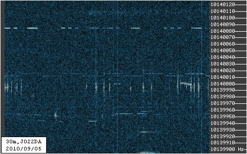 |
| 40m average |
Saturday, September 4, 2010
QRSS Averaging vs Plasma TV - 2nd Test
Short update on averaging fighting a plasma TV.
I selected the best and the worst of the 10 frames used for averaging. It seems that every plasma TV has got its own finger-print...
Let's have a look:
This shows, as long as the local noise is regular enough, one can either simply ignore it, or fight it with simple measures. I think, I could do better on the dark frame story, however, I still lack pure TV signal to create my "plasma frame".
UPDATE
6 frames stacked (no dark frame), positive QRSS identification of "SGT" despite the plasma TV... more to learn. I should make my dark frame soon.
I selected the best and the worst of the 10 frames used for averaging. It seems that every plasma TV has got its own finger-print...
Let's have a look:
 | ||
| best frame |
 |
| worst frame |
 |
| average of 10 frames |
 |
| ... using the (old) dark frame |
 |
| ... dark frame and cut "low" pixels |
UPDATE
6 frames stacked (no dark frame), positive QRSS identification of "SGT" despite the plasma TV... more to learn. I should make my dark frame soon.
 |
| positive identification of SGT |
Subscribe to:
Posts (Atom)