Bought myself a new receiver for Christmas. Yes, yet another one. Here's some blabla about my first impressions.
For €199.- the package contains, the receiver (oh well...), some earphones and a 110/230V power supply with an adapter for American sockets. OK, and a very short manual.
When first attempting to engage... nothing... ???? Ahhh, by factory default, the keys are locked. That was a surprise, honestly.
There are a couple of features not really standard to such receivers. One is RDS which can be used to automatically program the internal clock. Interestingly enough, the clock can be set to two time zones and daylight saving time can be toggled by a single key. Speaking of "FM", the tuning range is 76 to 108MHz. There are two memory pages for FM, which can be programmed automatically (aka. ATS) by a single key.
The ATS also can be used for medium wave and long wave. The feature scans the respective band and stores the strongest stations to memory channels.
The MW channel spacing can be selected to 9kHz or 10kHz at a well accessible switch on the right side panel. This side panel also carries switches for "auto time set", "tone" (news/normal/music) and AM bandwidth next to a potentiometer for volume and a rotary tuning encoder.
The left side panel houses connection for DC, headphones, line-out, record trigger and external antenna. Also to be found, a potentiometer for RF gain (nice touch!).
Now to the more interesting things, short wave and first impressions as a grabber receiver.
Frequencies can be selected in a couple of ways, hacking it in by using the key pad, up and down tuning keys (5kHz steps) or the rotary encoder on the right side panel. The steps of the encoder can be toggled between 1kHz/40Hz in SSB mode and 5kHz/1Khz in AM mode, a third position disables the encoder. Since fine tuning in USB/LSB is 40Hz, there is no need for a clarifier, which therefore is not present.
When tuning, the receiver mutes whenever the frequency changes by 1kHz, even when using 40Hz steps. Within the kHz, the receiver does not mute. Seems some PLL locking.
One interesting feature is the memory system. Whenever a frequency is typed in which is stored in somewhere, the memory system changes to the memory page which the frequency is stored in. The mode is change to the stored mode.
During the first night, the receiver was very unstable and drifted a lot, the QRSS test was very difficult, doubts raised on the usability of the receiver for QRSS. The major drift was in one direction only and slowed down with time. That made me believe that this drift was due to fresh components which were not aged. The second attempt was going much better, the gadget was left one for the best part of the day. Before the test, I switched it off for a couple of hours, to see the effects of the warming up. Stability is much better now than it was during the first test.
BTW, for QRSS the RF-gain feature proved itself as very useful.
I hope that further use will further age the frequency determining components and thereby increase the frequency stability. If that will happen, the ATS 909 will make a really nice portable grabber setup.
Thursday, December 31, 2009
Sunday, December 27, 2009
Receiver for 7059900Hz
Several obvious options here.
SDR using 4x the qrg. Here, we a got crystal from Nick, 28.188MHz, resulting in an SDR center frequency of 7.047MHz. Alternatively the canned 28.322MHz-oscillators provide a center frequency of 7.0805MHz.
SDR using half the receive frequency, phase shifting of 90 degrees done by an RC circuit. A crystal is available: 3.535MHz (from Rich). This results in an SDR center frequency of 7.070MHz.
And finally, there is a crystal available, from box73.de, having a frequency of 3.530MHz. This is too close for SDR, but allow for a subharmonic direct conversion receiver, more or less in the same way as I use it for 30m. The only drawback here, there is not 7.060MHz crystal yet, hence, no easy way for a sideband filter. However, there are crystals for 7.055MHz (Rich, box73.de) and 7.058MHz (Rich), which could serve as a notch filter, just like in Gene Marcus 30m WSPR transceiver.
Sunday, December 20, 2009
20m FSK/FM MEPT
Design idea here: use as much of the 74HCT240 as possible. Hence, one inverter as oscillator, three buffer (I know, this does not really make sense, but wait!) and the block of the other four gates as power amplifier, all four in parallel for use with a step-up transformer. The "PA" is equipped with an enable/disable switch.
So, here is comes, why use three buffers. Well, the first buffer is required since oscillator gate is operated in "linear mode". This first buffer inverts the signal, or in other words, phase-shifts it by 180 degrees. The second buffer inverts the signal again, providing a signal which is phase-shift by another 180 degrees, delivering an in phase signal to the oscillator. Who knows what this can be used for...
OK, now the third buffer seems really useless, but, it is not ;-) This buffer terminated the second one properly, so that always a nice signal can be drawn from either buffer 1 or buffer 2.

Sunday, December 13, 2009
Astronomy meets QRSS
Inspired by last nights experiment, I suggest the following:
Let's transmit in predefined time slots, as the IBP-beacons.
This could be used for the following procedure:
- start a grab a some 10secs before the slot, and end it some 10sec after the slot
- put the spectrum in a file named after the slot + sequence number
- register and stack all files of a single slot (as it is done in modern astrophotography)
The question is, how to automatize this. I'll look into this...
Benefits, extreme noise reduction due to integration over a longer period, as done in astronomy. (check my astronomy stuff at www.qsl.net/dl1gsj - webcam imaging with small telescopes).
Friday, December 11, 2009
Wednesday, December 9, 2009
E-probe experiment (30m)
The Suburban Subharmonic Grabber uses a wider than 100Hz range.
Hence, occasionally a WSPR station makes it into the visual
(displayed) spectrum. When I did my E-probe test, under comparably
poor condx on 30m, RW6XC came up, low enough to nicely be seen
on the grabber spectrum. The interesting part, a visual spectrum
of a single station can be compared to the signal to noise ratio
determined by the WSPR software.
Have a look:
 Date: 2009-12-09
Station monitored: RW6XC
Power (indicated): 5W
Distance: LN23AS -> JO22DA = 3059km
UTC...SNR
19:58 -20
19:46 -24
19:38 -20
19:34 -19
19:30 -15
19:26 -14
19:22 -12
19:16 -7
19:12 -8
19:08 -7
19:04 -11
19:02 -12
19:00 -19
The other part of the test was, to see if and how many
station are received by this minimal setup. Remember,
this is an E-probe feeding a homemade direct conversion
receiver...
Stations received during 24h using the E-probe:
Date.......UTC...Call...SNR.Loc...pwr.km.
2009-12-09.17:12.W1XP...-25.FN42fo.5.5546
2009-12-09.19:58.RW6XC..-20.LN23as.5.3059
2009-12-09.10:28.RA3ZSE.-19.KO80ws.5.2313
2009-12-09.13:40.OK2SAM..-9.JN99du.1.1008
2009-12-09.13:46.OE3EV..-12.JN88...5..981
2009-12-09.13:42.IQ4DJ..-12.JN54mq.1..955
2009-12-09.09:50.GM4KGK..+1.IO68ve.5..955
2009-12-09.11:32.OK2BUH..+3.JN89oo.5..945
So, second experiment, yes, you can receive stuff with absolute minimal gear...
Tuesday, December 8, 2009
indoor DCTL & WSPR on 30m
This is what my tiny subharmonic d.c.-rx heard when wired to the indoors DCTL.
| Timestamp | Call | MHz | SNR | Drift | Grid | Pwr | Reporter | RGrid | km | az |
|---|---|---|---|---|---|---|---|---|---|---|
| 2009-12-08 03:36 | W3HH | 10.140158 | -24 | 0 | EL89vb | 1 | PA1GSJ | JO22da | 7276 | 42 |
| 2009-12-08 13:40 | W1XP | 10.140242 | -17 | 0 | FN42fo | 5 | PA1GSJ | JO22da | 5546 | 51 |
| 2009-12-08 14:24 | RW6XC | 10.140147 | -19 | -1 | LN23as | 5 | PA1GSJ | JO22da | 3059 | 302 |
| 2009-12-08 09:46 | I0/N2CQR | 10.140152 | -24 | 1 | JN61fv | 0.02 | PA1GSJ | JO22da | 1283 | 334 |
| 2009-12-08 08:54 | F6EZP | 10.140189 | -20 | 0 | IN93 | 2 | PA1GSJ | JO22da | 1029 | 21 |
| 2009-12-08 07:36 | OK2SAM | 10.140199 | -23 | 0 | JN99du | 1 | PA1GSJ | JO22da | 1008 | 289 |
| 2009-12-08 07:30 | OE3EV | 10.140193 | -6 | 0 | JN88 | 5 | PA1GSJ | JO22da | 981 | 298 |
| 2009-12-08 07:42 | IQ4DJ | 10.140228 | -5 | 1 | JN54mq | 1 | PA1GSJ | JO22da | 955 | 331 |
| 2009-12-08 09:44 | GM4KGK | 10.140281 | -6 | 0 | IO68ve | 5 | PA1GSJ | JO22da | 955 | 131 |
| 2009-12-08 10:10 | OE3WGW | 10.140178 | +9 | -1 | JN88cj | 5 | PA1GSJ | JO22da | 937 | 300 |
| 2009-12-08 09:40 | IK1ODO | 10.140264 | -19 | 0 | JN35sa | 20 | PA1GSJ | JO22da | 814 | 344 |
| 2009-12-08 10:34 | DL5MHD | 10.140212 | -9 | 0 | JN58xc | 5 | PA1GSJ | JO22da | 699 | 311 |
| 2009-12-08 10:34 | DG7RJ | 10.140240 | -23 | 0 | JN58th | 5 | PA1GSJ | JO22da | 665 | 311 |
| 2009-12-08 10:46 | HB9TMW | 10.140144 | -25 | 1 | JN36gq | 5 | PA1GSJ | JO22da | 615 | 345 |
So folks, here you have it, you can receive weak signal living in a concrete building in a dens suburban environment.
In another experiment, I will use the E-probe, outside at my balcony, stay tuned for the data.
new low frequency ideas part 2 (RX)
There is another added bonus on CB crystals for low frequency operation. At least for the 136kHz band.
A CB-channel 22 TX crystal (27225kHz) would result in a frequency of 138.9kHz, just 1.1kHz off the upper band edge and 3.2kHz off the lower band edge.
Given the fact that the two last frequency divisions (see the earlier blog entry) resulting in 4 (two flipflops) it appears somewhat obvious to use just this crystal in a direct conversion SDR receiver.
new low frequency ideas (TX)
Working with dividers seem to have advantages to me, amongst: greater stability and easy digital design. The only question is, are there enough crystals in a close range?
Well, what about old CB crystals? And how would those get us onto the 136kHz band?
First things first!
Here is what I came up with and how I started the process:
There is an industrial crystal 27000kHz crystal, divide this by 196, get us to 137.76kHz, just 60Hz off the QRSS COA (center of activity).
How to divide by 196, well, that actually easier than I though:
- 196/2=98
- 98/2=49
- 49=7*7
The recipe is hence, two counters to 7 in series (so that they multiply) and two FlipFlops. There we go, a 50% duty cycle with a cheap crystal in the middle of the QRSS range. Drift should not be an issue here, assume, the oscillator drifts by 1kHz, that would result in a 5Hz drift on long wave.
I think, there is even a canned oscillator of that frequency, making the design in particular simple.
And now to the added bonus: CB-XTALs!
I reach in my junk-box to see what crystals I got from old CB radios. Some calculation revealed the following:
- 26600/196 = 135,71
- 26610/196 = 135,77
- 26620/196 = 135,82
- 26630/196 = 135,87
- 26650/196 = 135,97
- 26660/196 = 136,02
- 26670/196 = 136,07
- 26680/196 = 136,12
- 26780/196 = 136,63
- 27000/196 = 137,76
- 27005/196 = 137,78
This covers essentially the whole 136kHz band with junk crystals from CB radios. Even better, look at the channel count, to me that looks like I will be using the casing and the channel selector too ;-)
I missed a couple of frequencies, since I got no crystals for those in my junk box.
The internet discloses that there are RX crystals for the CB channels 8 to 40 ranging from 26600kHz to 26950kHz with 10kHz increments, a few channels skip however. 10kHz steps will result in 51Hz steps in the 136kHz band.
Additionally, there are TX crystals for CB radios. CB channels 1 to 4 (26965kHz to 27005kHz) would be interesting here.
One may consider to experiment with VXOs, since old CB radios have those anyway, ranging +/-5kHz, which would the cover essentially the whole band, with just a few gaps due to the lack of crystals.
The same principle could be serving for the 500kHz band. Here, one would require a division by 54, which would be two counters 9 x 3 = 27 and one flipflop => 54. CB TX crystals from upper channels could be used. Since I don't hold a licence to that band, I will not look any deeper into this. Nevertheless, I hope, that someone finds this useful.
Monday, December 7, 2009
80m results (06.12.2009)
Colin and I did some tests on 80m lately. The following spectrum shows the final minutes, before Colin QSYed. Receiver setup on my side: NASA Target HF3 + E-probe. The computer used for analysing is a Packard Bell "dot" netbook with an Intel Atom N270 processor.
The darker regions on the spectrum are due to a local (The Hague) sideband station pulling the AGC to the max. But still, there is some F1A (FSK-CW) coming through... The cheap'n easy setup still allows for detecting weak signals...

The darker regions on the spectrum are due to a local (The Hague) sideband station pulling the AGC to the max. But still, there is some F1A (FSK-CW) coming through... The cheap'n easy setup still allows for detecting weak signals...

Saturday, December 5, 2009
136kHz ideas
Some considerations to generation of frequencies in the region of the long wave band using counters and cheap crystals. The first number is the resulting qrg in Hz, the second number is the crystal frequency in MHz and the third number is the divider/counter.
Additionally, there are some approaches mixing different frequencies, I will not go into this in the present note.
The trick is to end the chain of dividers with a division by two, creating a 50% duty cycle.
I would like to point your interest to some frequencies for which ceramic resonators are available. Those could be nicely pulled, given the ratios, the stability of a ceramic resonators oscillator seems OK-ish to give some results still. Assume 1kHz drift @ 5.5MHz. This would resulting in a 25Hz drift @ 136kHz, not desirable, would allow for first tests however. It is clear that care should be taken to avoid drift all together.
For crystals, one could consider moderate super-VXOs.
At the end of this message, a band plan is attached. Some frequencies I listed are actually outside the band, consider this as a hint to SDR-receivers, in particular when the last division could be by 4.
There are two candidates for QRSS marked in red. However, both require a division by 13 :-(
Simple solution "ripple counters"
One decade counter + ripple counter or flipflops
Two decade counters + ripple counter or flipflops
Ceramic resonators
Now, what to select, taking into account the band plan:
Additionally, there are some approaches mixing different frequencies, I will not go into this in the present note.
The trick is to end the chain of dividers with a division by two, creating a 50% duty cycle.
I would like to point your interest to some frequencies for which ceramic resonators are available. Those could be nicely pulled, given the ratios, the stability of a ceramic resonators oscillator seems OK-ish to give some results still. Assume 1kHz drift @ 5.5MHz. This would resulting in a 25Hz drift @ 136kHz, not desirable, would allow for first tests however. It is clear that care should be taken to avoid drift all together.
For crystals, one could consider moderate super-VXOs.
At the end of this message, a band plan is attached. Some frequencies I listed are actually outside the band, consider this as a hint to SDR-receivers, in particular when the last division could be by 4.
There are two candidates for QRSS marked in red. However, both require a division by 13 :-(
Simple solution "ripple counters"
- 138550 = 4.433619 / 32 (=8x4=2x2x2x2x2)
- 138550 = 8.867238 / 64 (=8x2x4=2x2x2x2x2x2)
One decade counter + ripple counter or flipflops
- 136533 = 9.8304 / 72 (=9x2x2x2)
- 137500 = 22.000 / 160 (=10x8x2)
- 138240 = 22.1184 / 160 (=10x4x4=10x4x2x2)
- 136533 = 4.9152 / 36 (=9x2x2)
- 138888 = 5.000 / 36 (=9x4=9x2x2)
- 138888 = 10.000 / 72 (=9x2x2x2)
- 144444 = 5.200 / 36 (=9x4=9x2x2)
- 136533 = 6.5536 / 48 (=6x2x2x2)
- 136533 = 7.3728 / 54 (=9x3x2)
- 136533 = 14.7456 / 108 (=9x3x2x2)
- 136533 = 16.384 / 120 (=10x3x2x2)
- 136550 = 2.4579 / 18 (=9x2)
- 136533 = 24.576 / 180 (=10x9x2)
- 136533 = 3.2768 / 24 (=6x2x2)
- 136533 = 3.6864 / 27 (=9x3)
- 136533 = 4.096 / 30 (=5x3x2)
Two decade counters + ripple counter or flipflops
- 136364 = 3 / 22 (=11x2)
- 136364 = 6.000 / 44 (=11x2x2)
- 137675 = 3.579545 / 26 (=13x2)
- 137675 = 14.31818 / 104 (13x2x2x2)
- 137255 = 14.000 / 102 (=17x3x2)
- 136364 = 15.000 / 110 (=11x5x2)
- 136364 = 18.000 / 132 (=11x3x2x2)
Ceramic resonators
- 137500 = 5.50 / 40 (=10x2x2)
- 138889 = 5.00 / 36 (=9x4x2)
- 138889 = 10.00 / 72 (=9x8x2)
- 136389 = 4.91 / 36 (9x2x2)
Now, what to select, taking into account the band plan:
- 135.7 - 136.0 kHz
- Station Tests and transatlantic reception window
- 136.0 - 137.4 kHz
- Telegraphy
- 137.4 - 137.6 kHz
- Non-Telegraphy digital modes
- 137.6 - 137.8 kHz
- Very slow telegraphy centred on 137.7 kHz
Grabber news: WSPR2 works
The new version of WSPR allows to set a RX BFO other than 1.5kHz. The usable range stops at 3kHz, just enough to use the subharmonic direct conversion receiver for spotting WSPR signals.
Assume the following: The mid-qrg of the WSPR band on 30m is 10140.2kHz. With a "BFO" setting of 1.5kHz, that gives the famous 10138.7kHz. The subharmonic receiver's LO runs on about 5068.8kHz (depending on the individual canned oscillator). Double that, it will give 10137.6kHz, resulting in a "BFO" frequency of 2.6kHz to reach the WSPR-band.
My resulting LO frequency is a about 69Hz further off, here comes a correction in, one has to measure first. For me, it results in a "Dial Frequency" of 10.137531MHz and a "Rx BFO" of 2669Hz.
Good news for WSPR-users, I will be now monitoring whenever the grabber is set to 30m.
Wednesday, December 2, 2009
30m DCTL as presently used for the JO22-grabber
Here come the numbers... (bonk bonk bonk!!! for the insiders):
- radiator total length: 327cm
- matching stub length: 46cm
For the radiator, i.e. loop, this is the actual wire cut length. Meaning, there's about 5mm vanishing into the luster terminal.
As for the stub, same story, however, the stub is shorted, and whatever is needed for that short is not taken into account by that figure. However, I believe, that this would not make a big deal difference in matching anyway...
This is, how stuff is wired up in my (experimental) setup:

The "matching stub" (current center of the loop) is connected to both terminals, either of the loop leads to the respective terminals. The whole thing is matched to RG58 by means of a 4:1 balun using a T50-6 toroid contraption (classic approach).
With this setup my MFJ-analyzer was showing a SWR of 1.2:1 @ 50Ohms. Fine with me. The loop is sensitive to its environment however.
Short note on how I resonated this loop. It was cut to a frequency much lower than wanted, since my aim was a single frequency loop for a grabber. Anyway, the 30m band is not that wide, or is it? With the analyzer engaged, I progressively cut off bits of the "voltage"-end of the loop, until I reached the aimed mid resonance frequency. This should be done symmetrically, in order to prevent noise caused by local E-fields (vacuum cleaners, hair dryers, etc.).
No toroid in the junk box? This could be an alternative to match TV-twin lead to 50Ohmx coax:

It was giving a slightly inferior result, hence, the T50-6 balun won and will stay connected with the grabber for the upcoming future.
DCTL demystified
This is an attempt to explain my understanding of the DCTL (Distributed Capacitance Twisted Loop) antenna. Personally, I am convinced to have understood its functioning. In a second blog entry I will provide detail for a 10MHz DCTL antenna, so you could build one yourself.
Let's start on a simple design of a self-resonant loop antenna. This concept is also known as frame antenna. A sort of magnetic loop without a capacitor but two windings instead. The two windings (parallel conductors) will provide a distributed capacitance which will form a parallel resonance LC-circuit, as we know it from regular magnetic loop antennae.
Let's assume, the feeding is done by a T-match, this would result in the following configuration (red=feedline):

The T-match as got two feed-points to the otherwise closed resonance LR-circuit. Those feed-points are marked in the following sketch:


Assuming that the conductor of the loop between the feed-points roughly matches the feedline's impedance (200-300Ohms), one could squeeze this section into a hairpin structure. The following sketch would reflect this...

OK, the loop is matched now, but what about the resonance? Well, if the loop is cut well, that is the end of the story! Why bother? Yes, really, this could be the end of the story if you intend to use the loop in a relatively narrow stretch of QRG.
However, here is, what was though about in 1994, the end result of the DCTL (as you may find it on the internet).
The sketch show a capacitive (open) stub which terminates the loop in a fashion known from magnetic loops. This stub adds a few pF only, and should be cut to the mid-resonance of the DCTL. The stub lowers the DCTL's frequency, hence, the DCTL has to be cut to a QRG above the aimed operation frequency. Finally, having a DCTL self-resonant, i.e. w/o capacitive stub, above a ham-band, allows for a kit of stubs to cover the whole band.

With this tiny post, I hope to focus your attention of a very portable antenna, which is almost forgotten, probably because it was never understood or decently explained in the first place.
Tuesday, December 1, 2009
bonk bonk bonk... (DCTL)
That would be the echo of me banging my head on the wall... Now that the thing is in resonance, it works brilliantly with my subharmonic direct conversion receiver. Grggrrrrrr, I took it for granted for several weeks, that the dimensions of the loop were ok, and put all efforts to the 6:1 balun... Now that I think of it more clearly (don't you ask me why this didn't happen earlier, you don't wanna know!), it is sort of clear, I am not using 300Ohms window line as I used for the 40m DCTL, but rather EUROPEAN (!!!!) TV-twin, which is 240Ohms (I believe), and thus, also has got a different capacitance per length.
Bonk bonk bonk ...
Bonk bonk bonk!!!!
But now, it seems, I am onto something. Receiving the mystery station from JN44AE now, 2037z.
The DCTL finally usable for QRSS? I hope so, I intended to use this sort of aerial for future journeys, to put signal in the air, or maybe receive occasionally...
Bonk bonk bonk ...
Bonk bonk bonk!!!!
But now, it seems, I am onto something. Receiving the mystery station from JN44AE now, 2037z.
The DCTL finally usable for QRSS? I hope so, I intended to use this sort of aerial for future journeys, to put signal in the air, or maybe receive occasionally...
hmmmm
Banging my head against the wall... stupid me!!!
The 30m DCTL, even with the new balun I produced this morning (before the O.P. @ work) did not perform. And guess what??? Now that I finally checked it out with my MFJ analyzer, it is resonant 500kHz lower, somewhere around 9.5MHz.... Yep, for a narrow-ish band antenna, this cant do the trick.... Oh man! I wonder how I received Andrew's MEPT with this thing in the first place....
Now, more cutting will be done, and I promise that I will have the aerial as successful as the big brother I once cut for 40....
Still banging my head....
Monday, November 30, 2009
Ten Tec kit 1340 mod
Having built the first (essential) stages, it's now time to decide on further deviations of the circuit and the way it is most intelligent to construct.
Remember, the idea is to use as much as possible from the kit to build a 40m QRSS transceiver.
First consideration, phase 1 completes the keying and rx/tx-switching. We need that, phase 1 should be built w/o any alterations.
Phase 2: this is the VFO & buffer, well, we don't want a VFO, we want an (TC)XO instead, hence, I propose to postpone any construction to a later stage. If you really want to do some soldering in that stage, that's seems reasonable to do: Q18, C33, C83, C84, R55-R59, L16. This is the last buffer stage with a low-pass. At the other C33 we will couple in the XO.
Phase 3: TX mixer. I believe, the transmit mixer should be postponed. Really. Let's first the the receiver operational and take care about the transmitter later.
Phase 4: RX front-end and filter. The front-end we really need, I suggest to build everything but the filter. Since the bandwidth we are interested in is just 100Hz, the idea is not to use all four crystals for the filter, but just a single one. Here, some experimentation from my side is still required.
Phase 5: BFO, RX mixer, audio. BFO and RX mixer we obviously need... What audio is concerned, the preamp-stage seem reasonable to build, up to C12. R6 could be replaced by a trimmer and the a.f. final skipped totally, finally we want to feed the signal to the computer.
My preliminary opinion on the AGC is not to include it. It could be turned into a manual gain control (using R6 feeding bias to Q7's base) or made switchable.
.
.
.
UPDATE: All those considerations brought me to a point where so few is left of the original kit, that it would be the best to start from scratch, w/o a kit, with a given bonus.
Considering the reverse, i.e. the intermediate frequency being 4MHz, and the L.O. being 11.0592MHz, one could actually see the rig serving both the traditional and the new QRSS frequency. And yes, I have to admit, I did see it in the first place, that the TT1340 would be serving the traditional frequency out of the box.
HENCE: For myself, I decided to build the TT1340 as intended by the designers, and home-brew a QRSS transceiver with the 4MHz I.F. approach.... In fact, this will be more like a superhet receiver and a MEPT, both having switchable TCVXOs (11.0000 vs 10.0592). Added value here, the MEPT could be FSKed at the 4MHz oscillator, allowing for better set control for the TX QRG.
Sunday, November 29, 2009
30m as my DC-RX sees it
A busy 30m band, and that's what the two diodes listen to. Sometimes other modes occur, but that's usual mix, PSK31, WSPR, QRSS and RTTY. Unknown noise band just across the qrss-section, does anyone have an idea what that could possibly be?
If you wonder why the spectrum is brighter at about 10.140MHz, I am using a single 10.140MHz crystal as front-end filter, tuned to the qrss-section.

receiver comparison
Short test this morning, all about receivers again. Usually, if there is no special experiment going on, I have my little diodes doing the receiving for my grabber. And so did those during the night, when we stopped the experiment on 20m.
Due to the 20m experiment, the AOR AR3030 (with Collins filters) still is close to the grabber computer. Thus, a quick look to compare the homebrew direct-conversion receiver to the commercial product. Same antenna (G5RV-jr), same matching, just another receiver.
Here's the result:

Some short explanation, around 0745z I decided to have a look on the grabber to see if something is dripping in. I reckoned that the brightness setting for the spectrum was a little on the darker side and therefore adjusted to the level I usually use. Around 0806z the receivers were exchanged, and sensitivity levels needed adjustment. Since both receivers deliver quite different a.f. levels, the spectrum on the d.c.-RX is essentially black at 0805z, this is due to the working of spectrumlab, whenever you used this software before, you will know what I am writing about.
The AR-3030 show a slight warming up curve, fair enough, I was off all night.
As for sensitivity and noise, I don't see much difference...
To me this is a very satisfactory result, given the d.c.-rx cost a fraction of the commercial receiver equipped with the finest of filters'.
I could, and probably will, give the FRG-100 a shot, however, the FRoG is not equipped with a narrow bandwidth filter.
Saturday, November 28, 2009
YES! (AT-120)
For some reason, life meant it good with me and let me obtain an article I long thought lost. An ICOM AT-120 :-))
The tuner suits my two marine radios, aka SSB radio telephones, IC-M700D and IC-M700TY perfectly. Could well be that the tuner will join one of the radios on board Pandia for /mm operations on 14.313MHz or PSKMAIL frequencies.
Most likely, the AT-120 will match Pandia's backstay, other configurations are thinkable however....
Thursday, November 26, 2009
HF3 clarifier adjustment second option
There are two ways, both not very difficult. Adjusting the clarifier takes some patience however, steady fingers help with an unmodified HF3. For the first option, please see the entry about HF3 grabber setup.
Here a second option that does not require a spectrum display, in this method you will be using your ears instead of your eyes. This is now it works, and also why...
Here a second option that does not require a spectrum display, in this method you will be using your ears instead of your eyes. This is now it works, and also why...
- pick a broadcast station or timesignal with proven stable frequency
- switch to USB (you should now here a 2kHz tone, that would be the carrier)
- set the dial 2kHz above the nominal frequency (this bring you close to zero beat)
- adjust the clarifier for zero beat
This is why this works, the HF3 has got a very wide side-band filter, I guess that saves the maker some money. Hence, the filter's passband is broad enough to even pass the carrier and LSB contributions, allowing us to adjust the clarifier w/o any further tricks.
Tuesday, November 24, 2009
XTAL filter for the grabber RX
Here is a spectrum to demonstrate the effectiveness of the single crystal filter employed in the 30m QRSS band d.c.-receiver. The filter is tunable by means of a trimmer capacitor.

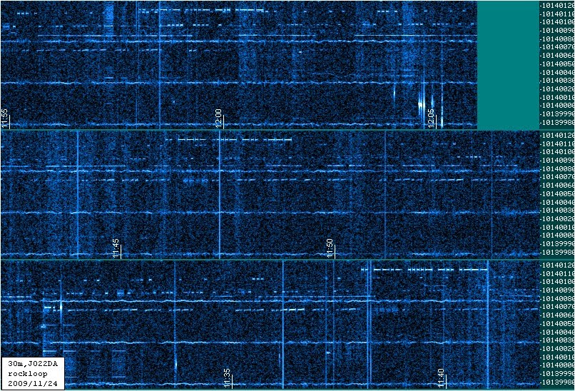
30m best of 2009-11-24
The following spectra were taken with an indoors rockloop (magnetic loop made from wire) and my homebrew subharmonic 30m direct conversion receiver (cf. my web-page).
From the awaking of the band to its closing, everything was in, Es short skip, regular skips and even DX (flying W) during daytime, closing finale with grey-line DX.


Three band MEPT, 3.5999MHz QRSS QRG update
Two subjects in one posting...
3.5999MHz:
Here are simple ones, I have not seen before:
Three band MEPT:
#1 of the above combinations has added value, since the 14.000 oscillator could be modulated, providing a 20m MEPT at the same time. At the same time, cf. an earlier post, 14.000 can be down converted to 7.0599MHz by means of a 15m QRP crystal.
Summarizing:
As for the QRP crystal, know your sources: Box73, ESS, QRP clubs, etc.
3.5999MHz:
Here are simple ones, I have not seen before:
- 3.6 = 14.000 - 10.400 = 14.000 - 2 * 5.200
- 3.6 = 14.400 / 4 = (2 * 5.200 + 4) / 4
- 3.6 = 7.200 / 2 = (5.200 + 2)/2
Three band MEPT:
#1 of the above combinations has added value, since the 14.000 oscillator could be modulated, providing a 20m MEPT at the same time. At the same time, cf. an earlier post, 14.000 can be down converted to 7.0599MHz by means of a 15m QRP crystal.
Summarizing:
- 80m: 3.5999 = 14.000 - (2 * 5.200)
- 40m: 7.0599 = 21.060 - 14.000
- 20m: 14.000
As for the QRP crystal, know your sources: Box73, ESS, QRP clubs, etc.
Monday, November 23, 2009
30m subharmonic DC-RX improved
Today's grabbing results were OK-ish. Not really good, however, the additional r.f.-stage helped, however, the shift the filter frequency prevented the break through.
The 22pF I experimentally confirmed for the version w/o the additional stage are now shifting the filter response far more upwards than wanted. To be more flexible, I decided to replace the 22pF capacitor by a trimmer capacitor with a maximum capacitance of 18pF. The first results are promising. The filter response is now centered to 10140050Hz, which hopefully provides much better reception than I gained with the last design....
Wish me luck!
3.5999MHz QRSS QRG update
Reaching in my junk box, I could not find a 6.400MHz crystal :-( Yes, they can be ordered... however....
What I found instead is even nicer, a 9.600MHz crystal, together with a 6.000MHz one, even in one bag. The 9.600 xtal looks like I salvaged it once from something. I would not recall what, possibly some obsolete network gear.
I guess, the design of the 80m secondary frequency MEPT is hereby decided. Nice in this is, with actually using the difference, some drift cancels out.
3.5999MHz QRSS frequency
Having had my brains chewing on the problem for a while, the solution is really obvious, sort of.
Remember, the task is to generate a frequency of 3.5999MHz, using cheap and available components.
And here it is:
FSK by pulling on one of the crystals.
In my design, I would probably pull one crystal for modulation and the other for the TX frequency.
Now, that was not that hard, or was it?
Remember, the task is to generate a frequency of 3.5999MHz, using cheap and available components.
And here it is:
- generate 6.400MHz
- generate 8.000MHz
- mix! => 14.400MHz & 1.600MHz
- filter ...
- divide by four (FlipFlops) => 14.400MHz/4=3.600MHz
- filter ...
FSK by pulling on one of the crystals.
In my design, I would probably pull one crystal for modulation and the other for the TX frequency.
Now, that was not that hard, or was it?
Sunday, November 22, 2009
HF3 grabber setup

This is what the present grabber setup looks like. The difficult thing is to adjust the BFO such that it is clear where it is. This receiver will not be modified, however, there is a second of this make on the way into my shack. One of the two will be modified, severely ;-)
The grabber is set to listen to QRSS signals on 3,599,900.0Hz. This may look odd, but, the HF3 is not aimed at radio amateurs, it is aimed at yachtsmen (like me). It particular to receiver TTY weather reports, weather charts via FAX, NAVTEX and occasionally some news on HF-BC using A3E. In marine station listings, the frequency for teletype stations given is the frequency between mark and space. To help the sailors, the processor of the radio sets the radio's PLL to the dial frequency for A3E and 2kHz below for J3E/USB. I have not checked J3E/LSB yet, since it is of no importance to me.
When using the HF3 as a grabber receiver, I thus set the dial to the actual frequency I want to listen on, knowing about the 2kHz difference.
To adjust the clarifier, use a time signal, or a known to be stable BC station, to adjust the carrier such that it precisely results in a 2kHz tone.
I tell spectrumlab the dial-frequency minus 2kHz as offset, in this example, it would be 3,597,000.0Hz.
The FRT-7700 makes a good general purpose tuner. It helps to improve all sorts of mis-matches.
Saturday, November 21, 2009
Icom IC-M700D mod
Recently, I obtained one of those, the IC-M700D. This radio has got a "Posthörnchen" on it, meaning that the FTZ (Fernmeldetechnisches Zentralamt) gave its blessings. This however means, the radio does not do what it is not supposed to, i.e. transmit outside the marine bands.
Luckily, there is a service manual for the IC-M700 (no D!) available on the internet.
Browsing through the circuit description reveals that LOGIC CIRCUITS holds on control of the receive and transmit frequencies. The manual further recites that IC1006 outputs signals "mute signals for outside the marine bands to P40&P41. Ah! In the schematics diagram, P40 & P41 (pins 7&8 of IC11006) enable a voltage called "TMU" via transistor Q1003. The schematics diagram further shows a wire bridge W1037 shorting the base of Q1003 to ground. Hmmmmm, with W1037 installed, the transistor is never engaged to release the TMU voltage. Could TMU be an acronym for Transmitter MUte?
Let's have a look:

Let's have a look:

This is how the LOGIC CIRCUITS section looks in its original state:
 Note the cut wire, just above the label Q3. That's the cut W37.
W37 aka W1037 reinstalled here. And yes, the radio now switches to transmit on all frequencies. Hard to find, easy to fix.
I hope this will help amateurs since the IC-M700D presently still is very cheaply available, because it does not transmit on amateur radio frequencies... or does it?!
Despite the above success story, the radio by default only is equipped with USB. Yes, the mode switch does have two J3E-positions, however, they both do the same. I will have a closer look into the circuit if there is an easy way to get the BFO to oscillate for LSB too. For the case there is none, the casing provides enough space to add a pulled CB-crystal to add a BFO for the lower side-band. After all, the I.F. is 9MHz ;-)
Friday, November 20, 2009
E-probe vs TV noise
Here a spectrum, taken just when I switched from the G5RV-jr (left side) to the E-probe (right side). It is clear, the TV is still on, less prominent. Colin's trace remained about the same...

The decision is thus made, for 80m, I will use the E-probe.
Thursday, November 19, 2009
HF3 the Second
It was a toy in the beginning, the more I use it, the better I like it! Actually, I like it that much that I ordered a second one.
There are plans for this second one. Since there is a lot of space inside its' housing, there is room for modification and experimentation. Many years ago, I heard about a kit that converts a FRG-7700 into a transceiver. Cool, I thought, and forgot about it again. And now, the idea is back, with something that connects in either of the two, the FRG-7700 or the HF3. Both are double conversion superhets, both use a lower intermediate frequency of 455kHz. Using the generated frequencies, one could imagine to convert a single side-band signal all the way back from 455kHz to whatever the receive frequency would be.
I figure, it would be the question of just some NE612 mixers and two crystal filters, one for 455kHz (side-band) and one for the first intermediate frequency.
One further could consider to add some temperature control to the reference oscillator.
And, who knows, maybe this could be an easy way of producing some QRSS-signals too.
Monday, November 16, 2009
Roll your own!
This is about my newest addition to the spectrum grabber installation. The regular reader will know, that I was mainly using my rockloop (see webpage) for the 30m suburban subharmonic grabber. My rockloop is, however, a multiband (15m to 40m) aerial, which provided me with enjoyable QSOs in its' entire bandwidth. OK, I could build another one, but than again, multiband?
Years ago, I learned about the DCTL (Distributed Capacitance Twisted Loop) antenna. Actually shortly after its' design has been published. To that time, I cut myself a version for 40m from 300Ohm window-line. This loop actually never worked... well, at least not to that point in time.
Just recently I found the bag in which the DCTL was rolled up for storage. That brought the thought that I may possibly made a mistake when making the loop. And yes, in fact, I made a mistake, I forgot the "twist" in it.
Some months ago, I thus fixed it by soldering the leads together which belong together... and... voila, a working 40m DCTL. So far, so good, rolled it up again a was busy doing other stuff.
And now, just recently, I remembered it again (actually I just wanted something to print, in order to test my print-server setup). Only God know why I was hacking "DCTL antenna" into the average search engine and printed just the first thing that popped up:
Now, that would form a nice and cheap receive loop for the grabber.... And yes, it does!
Here come the dimensions of my 30m DCTL (please refer to the link above to understand what I am writing about)
- Ll = 347cm
- Lz = 46cm
- Lc = none
The lazy dawg I am, I could not be bothered yet to include a balun in the design, I am thus sipping the signals off the loop by means of ordinary RG58 coax. Yes, I do consider using TV twin lead as feedline, however, the stuff is rare nowadays, and I'd therefore probably rather wind a balun.... We'll see....
My 40m version is good for TX, I guess, the 30m version will be as well. I will try to tune (trim/cut) it accordingly and give it a try during my next journey.
Roll it up, roll your own!
Potential QRSS frequencies
Since in the US, only the extra class is allowed to transmit on the first 25kHz of the bands, our present habit of using the lowest edge of the traditional five shortwave bands prevents a majority of American hams to actively participate in very slow activity. This is the present situation, I believe:
For 80m, we could consider 3.5999, the border between narrowband and broadband data. An alternative could be the color burst frequency, 3.579. According to the region 1 band plan, this still is a CW frequency, however, massive PSK31 threat. Further pulling, we could possibly end up at 3.575.
Bands 20m and higher, I would suggest to stay close to the IBP beacons, something like 14.0989, 18.1089, 21.1489, 24.9289. For 10m, we got the nice 28.188 crystals made by Nick, so we should use those, I reckon.
For 160m, I would vote for 1.8432 since we got cheap crystals here, and some are operating MEPTs on that frequency already.
Don't forget, there also is the Italian frequency 28.322. Following this approach, and since it has been done before, we can cover 14.31818 with cheap computer crystals/oscillators.
Oh, I did not mention 30m and 40m ;-)
Well, I think, there's no need to change anything on 30m (10.140).
And as for 40m, an on-air test revealed that 7.0599 seems to be working fine. I will write about this "experiment" in the next few blog entries, stay tuned.
Summarizing, here's a list of suggested (new/additional) QRSS frequencies:
- 1.8432
- 3.500, 3.575, 3.579, 3.5999
- 7.000, 7.0599
- 10.140
- 14.000, 14.0989, 14.31818
- 18.1089
- 21.000, 21.1489
- 24.9289
- 28.000, 28.188, 28.322
Comments are welcome!
Saturday, November 14, 2009
IDEA ALERT (7059kHz & 14000kHz MEPT)
When writing my latest post on the KnightsQRSS-list, an idea shot through my head! Did not even require a lot of thinking :-)
A second, even more obvious, combination of available crystals fell out my fingers into the keyboard. Vy vy vy obvious, I even have both crystals in stock, for QRP and QRSS!
- 7059 => 21060 - 14000
Yes, there are cheap 14MHz crystals available (check here: http://www.reichelt.de/) and the 15m QRP-crystal should be in any of our parts collection anyway.
Here's, what I see, could be done:
A Pierce oscillator for 14MHz. This pulls the frequency up, so that we get into the 20m QRSS-range. For FSK, the 14MHz oscillator should be modulated. In practice, this is a ordinary 20m MEPT, no strings attached. Usually, one would expect the frequency to be 14000.800kHz
An oscillator with the 15m QRP crystal should be constructed such, that the frequency can be pulled downwards in a stable and controlled way to a frequency 21059.xxkHz. Let's make that 210593.
Now, all we need is a mixer, to subtract the 14MHz signal from the 21.059xMHz signal. Tiny downside here: the FSK will be inverted.
Such a design would provide a dual band MEPT. The thing, equipped with two finals and two filter stages, would even allow for simultaneous transmission on both bands.
A further idea is, to switch between the two bands according to the ambient light. This could be done by either the beacon keyer, a separate micro-controller or some analog contraption using OP-amps or transistors.
My personal favorite is the beacon keyer, since it would be rather simple to revert mark and space according to the band.
Now, where's my soldering iron???
Thursday, November 12, 2009
40m Novice QRSS QRG
I have not looked into any possible scheme of privileges, this is what I found:
There are a couple of obvious candidates for which crystals are available:
There are a couple of other reasons why I would suggest a frequency between 7.093 and 7.097. First of all, it is very simple to build an oscillator for 14.200 with a single crystal, pull it down a bit and divide the signal using a FlipFlop. The second reason I would see in the possibility to create a very simple superhet-receiver (or transceiver) with the combination found under point 4. This combination could also be used as a simple MEPT, however, drift is more an issue in a design using the sum of two frequencies.
This leads to the obvious advantages of the two combinations using differences. Once again, a superhet is possible and in a difference of two frequencies, drift is less of an issue.
- U.S. 7.025-7.125
- The Netherlands 7.050-7.100
- Germany none
There are a couple of obvious candidates for which crystals are available:
- 7.100 => which can be generated by a 14.200 crystal (ESS) divided by two
- 7.059 => 11.0592 - 4.000
- 7.085 => 12.000 - 4.9152
- 7.096 => 3.000 + 4.096
There are a couple of other reasons why I would suggest a frequency between 7.093 and 7.097. First of all, it is very simple to build an oscillator for 14.200 with a single crystal, pull it down a bit and divide the signal using a FlipFlop. The second reason I would see in the possibility to create a very simple superhet-receiver (or transceiver) with the combination found under point 4. This combination could also be used as a simple MEPT, however, drift is more an issue in a design using the sum of two frequencies.
This leads to the obvious advantages of the two combinations using differences. Once again, a superhet is possible and in a difference of two frequencies, drift is less of an issue.
I would go so far to state that there even is a kit for a transceiver, when 7.059 is considered. Well near enough at least. This rig would allow for transmission as well as reception.
The Ten-Tec 1340 is having an intermediate frequency of 11.000MHz. A VFO generates a signal around 3.97MHz.
And here comes the mod to the kit:
And here comes the mod to the kit:
- replacing all 11MHz crystals by 11.0592MHz xtals
- not building the VFO but an oscillator with a 4MHz xtal including a varactor for FSK
For QRSS I believe one would like to reduce the drive to the PA, since the final produces about 5W rf and would probably become hot in time. Maybe the final (2SC2166) could be left out all together. The driver is indicated to deliver 15dBm.
Further, the audio amplifier (LM386) could be left out in its entirety.
Wednesday, November 11, 2009
xmas today!
Two deliveries dropped in today :-)
- the PSK30 kit by K1SWL
- a 28.188MHz from VK1AA
My thanks go to both OM for their excellent services!
Tuesday, November 10, 2009
IC-M700TY qrv
Pandia is out of the water... I wanted her to stay in, but... the anti-fouling paint is essentially gone, the painter forgot to apply primer on top of the gel-shield before rolling on the copper-stuff...
No comment... thus, Pandia is out of the water for winter, giving me the chance of doing some work on the hull and on other part otherwise difficult to reach.
All right, now, what's that to with radio? Well... what about installing some aerials in the rigging?
Hard cut here; the exercise motivated me to wire up the recently obtained Icom IC-M700TY for the first time. The radio is superb! Never before I had the privilege to experience a noise blanker that actually works, well, the radio has got one. The squelch (on SSB!) works well, it's just a switch, I will have a look at the schematics, my impression was, the squelch seems to be dynamic, flip the switch and after a certain while the receiver is silent. The AGC is very effective, it cannot be influenced. Therefore I think, the radio is (w/o mod) not really suited for QRSS. The radio is controlled by a "high precision" TCXO, whatever that means. Said TCXO however is about four times the size of a TCXO in an amateur transceiver.
Downside, one needs to know the frequencies one wants to operate on. We amateurs tend to flip over a range of frequencies and see what's on. Well, spinning a knob in order to scan the band is a no no with the IC-M700TY. Actually, scanning is, compared to more modern professional (marine) radios, not an option to this radio. Thus, know what you want and which qrg to want it on.
I assume, the IC-M700 is ideal for modes such as PSK31, Pactor, etc. and further for nets and similar channelized voice operations.
Friday, November 6, 2009
IC-M700TY
Yes, today it dropped in. The radio is in wonderful condition. I think, it has never seen any ship from the inside.


Wednesday, November 4, 2009
Polyakov I/Q-SDR update
Some success but some fall backs too. The regular reader will know, I was working on a subharmonic SDR design for a while, with decent breaks however.
The design involves a 5.0688MHz canned oscillator, two pairs of anti-parallel diodes and some audio amplification (TL082).
Theoretically there also is a front end with a J310, but, it is not working, God knows why... need to look into this... Not oscillation, no attenuation, no amplification, no nothing....
I/Q works, however, the correct phase-shift adjustment is not easy, three parameters to play with. The sideband suppression (image canceling) is surprisingly good, with the proper phase-shift.
Presently the fun is spoiled by a major 50Hz contribution, I've seen that before, proper tins required ;-)
Sunday, November 1, 2009
Saturday, October 31, 2009
FRT-7700
This is stone-age stuff. But yeah, why not. Have been to a radio flea market today. With no further wishes on my list, it was some sort of gamble, the ride took me 1h30min each way, road construction, severe congestion, etc. The three hours in the car payed off however.
Presently the aerial of the Polyakov DC grabber receiver is matched by means of my QRP transmatch, which I actually do miss in my non-QRSS QRP work. Strolling along the lines of tables with used appliances, my attention was drawn to a table with communications receivers only. Not that I would be in need of any, really. However, there it was, a sole FRT-7700, shining into my face. The €40.- were payed without even attempting to negotiate.
Thus, soon-ish, the transmatch will again be wired up to something that also transmits and the QRSS spectrum receiver will have it's own dedicated antenna tuner. To be honest, not having it built myself makes me feel kinda odd. Could thus well be that the FRT will be replaced by something else; this something could well be a CLC-pi-filter, the classic.
Wednesday, October 28, 2009
30m QRSS-RX modification
Recently, I have seen some traces of lower sideband interference in my 30m-qrss receiver. Thus, the filter crystal went back in again. This time, with some experimentation and thinking. The crystal is now in series with a 22pF capacitor, pulling it just a little, such that the resonance is about the qrss band and a little bit above. Doing so, I hope to have removed contributions of the lower sideband.
22m Hifer RX (TX)
Super-heterodyne or not, that is the question. The 22m band is wide, that would not really encourage a superhet design with a crystal filter, at least not when all of the band is to be observed as a spectrum.
Thus, here come the crystal combinations (what did you think???):
- 6.5536 + 7.000 = 13.5536
- 6.5536 + 7.005 = 13.5586
- 6.5536 + 7.015 = 13.5686
Spot on, I would say. For a DC-RX, I would consider to slightly pull one of the crystal and mix. This would possibly enable to observe the full 22m range.
The superhet solution would probably point towards a 6.5536MHz IF, since those crystal are certainly cheaper.
The nice thing on this combi is, there is a ceramic resonator available (7.02MHz), which can easily be pulled in an oscillator circuit.
Source for the crystals and the resonator: box73.de
Monday, October 19, 2009
Yeah!
Yes, luck had it, I found an ICOM IC-M700TY and bought it :-))
The gear is perfect, really. It comprises the two maritime modes USB and F2B, but also A1A, A3E and LSB, which is unusual for maritime radios. This radio is intended for TOR (Teletype Over Radio).
As in all professional radios, there is no main dial (aka VFO-knob). The frequencies, RX and TX are independent, are selected numerically.
This is a no-nonsense professional radio, just like the one I was trained on for the General Operator's Certificate. The only difference here, no DSC. However, DSC could even be run externally, since the radio is prepared for TOR.
Sunday, October 18, 2009
Slow Train Coming
Not much progress on the DRM-RX yet, besides me looking into the gate design of TTL and LS-TTL NANDs and NOTs. BTW, both are almost identical. I wonder if it would be better to use open-collector gates when using the logic-circuits in analog mode... Browsing the internet, I only found standard TTL gates used. But most designs, other than oscillators, are making essentially use of the logic functions. Hmmmm, looks like I will have to hack things into SPICE, before continue thought on matters.
As Bob sings, "there's a slow train coming".
Thursday, October 15, 2009
DRM RX considerations
Some ideas settled into a first design idea.
I'll be using inverters, such a 7404, maybe LS.
The oscillator will be a Pierce design.
The attempt will be to use as many gates of the inverter linearised.
As soon as there's more, I'll provide an update.
I'll be using inverters, such a 7404, maybe LS.
The oscillator will be a Pierce design.
The attempt will be to use as many gates of the inverter linearised.
As soon as there's more, I'll provide an update.
Wednesday, October 14, 2009
On today's menu: DRM
Stumbled across some stuff, making me think I'd need to design and build a DRM-receiver. First ideas evolved; the design will be using (pulled) crystals and logic ICs.
Frequencies the receiver should be receiving, standard crystal frequencies provided:
Frequencies the receiver should be receiving, standard crystal frequencies provided:
- 3995 kHz (BBC/DW) - 4.000 MHz
- 6130 kHz (BBC/DW) - 6.144 MHz
- 3965 kHz (RFI) - 3.9321 MHz
- 5995 kHz (Radio Australia) - 6.000 MHz
- 6015 kHz (TDPradio) - 6.000 MHz
- 9850 kHz (Radio Prague) - 9.8304 MHz
- 11995 kHz (RDP Int.) - 12.000 MHz
- 1008 kHz (Economic. Ch.) - 2.048 MHz
- 1548 kHz (DW) - 3.0721 MHz
Saturday, October 10, 2009
FT-450 update
Had a little time to play with the radio. Actually, compared it to the IC-703, which is equipped with DSP too.
The FT-450 is able to digg out signals the IC-703 is not able to bring up. This caught me by surprise, sort of.
40m / 20m two band MEPT
- MEPT for 14.000800MHz
- QRP crystal for 15m (21.060MHz)
- => 21.060 - 14.000800 = 7.05992
- inverts!
Thursday, October 8, 2009
I could not resist... a sneak preview
That was me not posting, since I had my nose in the books, well, and wikipedia ;-)
The exam is written, new books did not arrive yet, no parties or other obligations... a perfect time to ... buy a new rig.
Which I did!
Now, there is an additional small big one sitting on my shelf. Small and big to the same time? Yep, I bought a Yaesu FT-450. Primarily w/o the internal tuner option. The very friendly dealer gave me the hint, that in fact buying the tuner-less FT-450 and the tuner ATU-450 itself later on will actually be saving money over buying the FT-450AT. We both agreed that this does not make any deeper sense, marketing-wise and could be explained by a stragetic error in Yaesu's HQ only.
Experience sofar, nice rig, however pretty useless without a manual! I guess, I will have to free space in the shack to allow easy access to the printed documentation. Some settings come along easy, for some settings one needs to dive deep into the menus. At a first glance, the rig seemed to be factory set to voice operators. Actually, I was even dissapointed with the CW capabilities at first. However, with the help of the manual, I am coming closer to settings which would satisfy my needs for comfortable A1A operations.
Things I liked directly:
Settings settings settings...
Thus, more on the radio, as soon as I understood more of the transceiver's main, extended and hidden menues.
The exam is written, new books did not arrive yet, no parties or other obligations... a perfect time to ... buy a new rig.
Which I did!
Now, there is an additional small big one sitting on my shelf. Small and big to the same time? Yep, I bought a Yaesu FT-450. Primarily w/o the internal tuner option. The very friendly dealer gave me the hint, that in fact buying the tuner-less FT-450 and the tuner ATU-450 itself later on will actually be saving money over buying the FT-450AT. We both agreed that this does not make any deeper sense, marketing-wise and could be explained by a stragetic error in Yaesu's HQ only.
Experience sofar, nice rig, however pretty useless without a manual! I guess, I will have to free space in the shack to allow easy access to the printed documentation. Some settings come along easy, for some settings one needs to dive deep into the menus. At a first glance, the rig seemed to be factory set to voice operators. Actually, I was even dissapointed with the CW capabilities at first. However, with the help of the manual, I am coming closer to settings which would satisfy my needs for comfortable A1A operations.
Things I liked directly:
- the key/paddle connects to the front face
- 3.5mm key- and phones-connectors
- nicely arranged display
- all dials positioned low
- flat "car type" fuses
- receives well below 100kHz (tested on DCF77)
- noise from the AF stage, even w/ volume set to minimum
- ATT on by default at lower frequencies
- single leads power-cord (not twin-lead!)
- tiny GND-connection screw
- a lot of the default settings
Settings settings settings...
Thus, more on the radio, as soon as I understood more of the transceiver's main, extended and hidden menues.
Saturday, September 26, 2009
Ahhh, another source of noise located
Remember that stupid line in the lower third of the 30m QRSS spectrum? As said before, earlier tests have shown that is was due to the built-in sound card. For a change, I wired up my two diodes to the rear Mic jack, and guess what? No stupid line. My system has got two built-in sound cards one of which is O.K., and the other is c###.
Sunday, September 20, 2009
Grabber RX back to DSB
Due to reduced sensitivity, the filter-crystal is back out again. Consideration here: we are looking at a bandwidth of 100Hz. The received LSB will be (about) 10135100Hz to 10135200Hz. According to this document, there is just the occasional Feldhell QSO, but other than that, the LSB range of the DSB receiver seems to be an empty spot.
Sunday, September 13, 2009
HB-1A qrp transceiver
Recently, well, several weeks ago, I came across a neat little radio from China, the HB-1A qrp transceiver. Tempted to order one. Up to now, I could resist.
Searching the internet for more information, I found a schematics diagram (dated 8-Aug-2009). From available information and some guesswork, that's what my understanding of the rig is.
Digital Part
The trx covers 5-16MHz using a DDS (AD9834) controlled by a 16F73. There is a keyer in a 12F629 and a MAX522 dac for generating voltage for the receiver's variable filters (more on that later). Finally, a serial eeprom is wired up to the main controller, which also runs the LCD.
Transmitter
Nothing worth to be mentioned here, the keying looks a little unusual to me... There is one thing interesting however, no mixing is done in the transmitter, although the receiver is a superhet. It appears that the frequency generated by the DDS for transmit is the in band QRG.
Receiver
Pretty straight forward NE602 / LM386 design. Muting is done by shorting out an attenuated (by a 2N7000) signal by means of a 2N3904. Here comes the first of the two variable filters, a tank-filter design using varactors driven by one of the MAX522's ports. NE602 front-end/mixer wired op to the DDS as LO. IF filtering is done by a variable bandwidth Cohn filter using varactors driven by the other port of the MAX522. A second NE602 used as BFO and product detector in the commonly known manner. The use of the LM386 is slightly unusual to me again, in particular the AF gain, or better volume control, which is done behind all amplification, with a potentiometer just before the phones jack.
No frequencies are given for the crystals, thus, my guesswork with some rough calculations came up with a likely IF of about 4MHz.
Here's some more of an actual owner: http://m1kta-qrp.blogspot.com/2009/08/hb-1a-qrp-tcvr.html
Thus, 4,1952MHz it is....
I am not quite sure if I understand the intention behind the relay placed in the low pass. If the transmitter would require an extra low pass filter, this could have been done directly behind the PA, overcoming the relay and in particular the noise it causes... clack clack de-clack...
Personally, I like the concept of the inclusion of the most important SW-BC bands. Seems like a nice companion for vacations, playing radio and receiving the daily news. Looking at the bands the transceiver covers (40/30/20), there will be propagation most of the time.
I was reading on an American page, that development seems to be going on for a version being capable of CW, SSB and DATA. Now, that sounds interesting!
Thus, I will wait for the time being, when ordering now, it wont be here for my next trip anyway.
But again, it's not really expensive... and why not... yeah well... hummm... we'll see about that ;-)
Sunday, September 6, 2009
off topic: AAO-110 accumulator charging (or not)
Strange, I thought, just a few months after purchase, the accumulators of my (several) Acer Aspire Ones (linux&win) seemed to have died. Hmmm, the one of the much older Eee4G still is doing fine. Very very strange, I thought, I tried to get free replacement from Acer, no success however.
Seems that I am not the only one having that problem. Internet revealed, it's not the battery that's gone dead, it simply the netbook not recharging it. In some micro-code, there's is something preventing the accumulator, when deeply discharged, to be recharged.
Actually Acer is aware of this, and made a new BIOS available, solving the problem. It is said that since BIOS version 0.3309 the problem is solved. I flashed version 0.3310 today, and yes, the problem is solved. The accumulators are charged again!
Up to now, I only flashed the windows one and gave an initial charge to the batteries used with the linux machines.
Thus, if you encounter a similar problem with the AAO (110/150), this could be your solution.
Subscribe to:
Posts (Atom)