Just an idea, which pop up when I replied to G4CWX and had a chat with PA9QV. The question was, what to use as a low power travel CW setup.
And this is the idea: a couple of RockMites in a box.
All transceivers could share the connector, i.e. antenna socket, control button, key. Band select, in my plan, would be a rotary switch powering up an individual transceiver PCB.
As said, just an idea....
And... I still got the RockMite kits for 20, 30 and 40m waiting for solder... the 80m version could be brought from QRSS to QRP... the 4-band-QRP-TRX would be completed.
Showing posts with label rockmite. Show all posts
Showing posts with label rockmite. Show all posts
Tuesday, August 17, 2010
Tuesday, February 2, 2010
RM80-MEPT, power measured
Terminated the MEPT with a 50Ohms 10Base2 terminator (boom boom!) and wired the whole thing up to my lab-TV.
The signal actually looked nice a clean, and was reading almost exactly 3Vpp. Some elementary maths would reveal the power being 22.5mW.
The signal actually looked nice a clean, and was reading almost exactly 3Vpp. Some elementary maths would reveal the power being 22.5mW.

RM80 first non-local RX
It may be hard to see, my bananas made it across the channel.


Those receptions show a very weakly coupled RM80 oscillator transmitting into an indoor frame antenna. I would call that a very low-profile setup. To complete the image, power measurements will follow.

Here is the prove.. that is what my local "control" grabber has seen:

Those receptions show a very weakly coupled RM80 oscillator transmitting into an indoor frame antenna. I would call that a very low-profile setup. To complete the image, power measurements will follow.
Sunday, January 31, 2010
QRSS RM80 final verdict (QRT)
Here's what you wanna do when going for a Rock-Mite-80-QRSS-mept/grabber.
- get a Rock-Mite 80 kit from Dave
- get two 3.579545MHz crystals
- get one 4.7pF and one 22pF capacitor
- build the kit, leaving out C8 (beep beep)
- for C12, use 4,7pF in place of 47pF (reduces chirp)
- for C2, use 22pF in place of 33pF (lifts filter response)
- get a 8-pin PIC (to replace U3) and program it as wanted
The reduced coupling from the oscillator to the (keyed) buffer results in lower output power. 4.7pF to me seems the working compromise. I tried all of the following values (in order of the experimentation timeline): 47pF (original - severe chirp, PA becomes hot), 27pF (still intolerable chirp, PA warms slightly up), 2.2pF (no chirp at all, nearly no power), 18pF (chirp), 10pF (chirp), 7.5pF (still too much chirp) and finally 4.7pF.
Optional, a 10V Zener diode could be dropped into D5's empty place. This will lower the "upper" qrg by about 200Hz, further reducing chirp.
For the mode, I would advice A1A with QSK, for timing, QRSS6 will do just fine.
Programming: With no further hardware modification, an 8pin PIC, such as the 12F629 can be used.
GPIO4 low will provide the varicap diode with 12V, resulting in the higher frequency, which is used for TX.
GPIO5 high will key the buffer and the PA.
I found that it is sufficient to low GPIO4 just before keying the transmitter. Returning GPIO4 to high directly after transmission allows for full QSK. No additional chirp in the TX signal.
To also receive, e.g. as a grabber, my program receives for 10min before TXing the message again.
I did all that, it works, concept proven.... hope to see more signals on the color burst frequency and more grabbers on the internet in the close future.
PS: Somewhat obvious... this mod will work on any frequency we got crystals for... e.g. 30m.
PS: Somewhat obvious... this mod will work on any frequency we got crystals for... e.g. 30m.
Saturday, January 30, 2010
Rock-Mite 80, update
The oscillator coupling is now done by 7.5pF. Additionally, a 10V Zener diode stabilises the varicap voltage. The latter step made the TX frequency to drop to 3579580Hz, according to PA9QV's grabber. Looks a little bit more stable now, and does not show this funky power up behavior...


In a further firmware mod, the TX QRG is switched to just before transmission so that the grabber is now QSK w/o that funky frequency shift. My impression is, that there is no impact on the stability of the signal.
Test on QSK, the strong carrier at '750Hz is the Ramsey, the 50Hz lines belong to it too (presently) for comparison, a view from my neighbor's grabber (Jan, you got a TV in your area too).


Friday, January 29, 2010
Rock-Mite 80, oscillator coupling
Just a tiny update. C12 is now 10pF, seems to put out some power, chirp is essentially gone.
I don't know why, but now the TX-QRG dropped to about 3579530Hz.
Hmmm, a bit later, the TX-QRG was up again ... ?!
I guess, I will need to wrap the thing into some casing of some sort.
I don't know why, but now the TX-QRG dropped to about 3579530Hz.
Hmmm, a bit later, the TX-QRG was up again ... ?!
I guess, I will need to wrap the thing into some casing of some sort.
Rock-Mite 80, further steps
The weak coupling from the oscillator to the buffer held the frequency comparably stable and nice, however, not much RF was radiated, my sigs made it into my neighbors RX and faintly some sort of trace.
Today, I increased coupling from 2p2 to 18p (orginally 47p), that again seems too strong, massive impact on the oscillator creating a really ugly but strong signal in my neighbor's grabber. Even the 2N2222's heat sink warms up now... Maybe reduce coupling again, to let's say maybe 10p ....


Today, I increased coupling from 2p2 to 18p (orginally 47p), that again seems too strong, massive impact on the oscillator creating a really ugly but strong signal in my neighbor's grabber. Even the 2N2222's heat sink warms up now... Maybe reduce coupling again, to let's say maybe 10p ....

I further changes the capacitor terminating the crystal filter, from 33p to 22p, seems to have some impact too:

Monday, January 25, 2010
Rock-Mite, PICAXE-mod
The Rock-Mite employs a 12F508 controller which is more or less pin-compatible with the PICAXE-08M which I intend to use.

Some modifications are necessary in order to use a PICAXE in the Rock-Mite.
The power amplifier is keyed from pin 2, obviously, the PICAXE bootstrap uses pin 2 for serial in, as shown above. TX keying therefore need to be rerouted to another pin. Fortunately, the line for keying is easily accessible. Now, "Serial In" and "Serial Out" (paddle dot) could form a programming port for the controller (three additional resistors).
When using pin 5 for generating PWM (frequency shift), pin 3 could be used for TX keying. With Q2 removed, the gate pad of Q2 could easily be routed to the TX-line, next to the crystal Y2. Hence, the original TX-line should be cut next to the source pad of Q2.
With this mod done, the RM should be fit for a PICAXE-08(M) controller.

Some modifications are necessary in order to use a PICAXE in the Rock-Mite.
The power amplifier is keyed from pin 2, obviously, the PICAXE bootstrap uses pin 2 for serial in, as shown above. TX keying therefore need to be rerouted to another pin. Fortunately, the line for keying is easily accessible. Now, "Serial In" and "Serial Out" (paddle dot) could form a programming port for the controller (three additional resistors).
When using pin 5 for generating PWM (frequency shift), pin 3 could be used for TX keying. With Q2 removed, the gate pad of Q2 could easily be routed to the TX-line, next to the crystal Y2. Hence, the original TX-line should be cut next to the source pad of Q2.
With this mod done, the RM should be fit for a PICAXE-08(M) controller.

I will post another photograph, as soon as I did the mod.
Rock-Mite 80, tiny change of plans
R18 will be just fine. For setting the output power, I will include a potentiometer between V+ and L1. So, do not yet solder in L1 at that stage. The potentiometer will be something in the order of 100 to 200 Ohms.
Sunday, January 24, 2010
Rock-Mite 80, first test
Here, the first oscillator test. Well, when writing oscillator, I actually intend to say that I only look at the oscillator's output, although there is only one part missing, preventing the power amplifier to amplify, namely R18 (as mentioned before).
The buffer seems to be working fine, when keying dots or dashes, the amp-meter of my power supply moves, good sign, I think. For seeing where the Rock-Mite is frequency wise, the HF3 + E-probe took the following spectrum.

What you see here, someone switched off their telly ;-) The carrier at 3579600 is the RM80's oscillator when the transceiver is not keyed. I keyed the transmitter twice with dashes and once with dots. You may realize that the line created by the dots is slightly wider, as one would assume.
The spectrum shows what the initial pull of the crystal is. Playing with PWM, we can be anywhere in between the two frequencies. I will perform another test with the Ramsey QRP80C in order to find out where this transmits w/o further tweaking.
I believe it would be most sensible to select our color burst QRPP-range according to what most kits will do OOB (well, when built that is).
And, btw, the Rock-Mite 80 was originally designed with a color burst crystal, as the supplied schematics suggest.
The buffer seems to be working fine, when keying dots or dashes, the amp-meter of my power supply moves, good sign, I think. For seeing where the Rock-Mite is frequency wise, the HF3 + E-probe took the following spectrum.

What you see here, someone switched off their telly ;-) The carrier at 3579600 is the RM80's oscillator when the transceiver is not keyed. I keyed the transmitter twice with dashes and once with dots. You may realize that the line created by the dots is slightly wider, as one would assume.
The spectrum shows what the initial pull of the crystal is. Playing with PWM, we can be anywhere in between the two frequencies. I will perform another test with the Ramsey QRP80C in order to find out where this transmits w/o further tweaking.
I believe it would be most sensible to select our color burst QRPP-range according to what most kits will do OOB (well, when built that is).
And, btw, the Rock-Mite 80 was originally designed with a color burst crystal, as the supplied schematics suggest.
Rock-Mite 80, first steps
The party was boring, hence I decided leave early and start building the kit instead. Actually, I essentially finished the Rock-Mite 80. Two parts I intentionally left out, C8 and R18. C8 feeds the side tone to the audio out and R18 is the emitter resistor of the 2N2222 power amplifier.
C8 is kinda obvious really...
As for the meaning of R18, it is a 10Ohms resistor and sets the rf-output to about 0.5W. I assume that with a 100% duty cycle, the little transistor would be pushed too far. A higher ohmic resistor seems therefore appropriate. A pot or trimmer in series to the 10Ohms resistor would allow for power control, which I believe is even more important.
The transceiver is now equipped with color burst crystals. There are two reasons for doing so, the observations we lately made demonstrated that 3.5795MHz is actually a really quiet frequency and crystals for this particular frequency are well available. Moreover, many QRP kits come with color burst crystals.
In a later stage I will remove R9 again. This 4k7 resistor supplies the varicap diode with V+. The plan is to feed a voltage generated by PWM (f-set and keying) into this point. BTW, the noise source (Zener diode) which is mentioned to be at this junction is omitted in the present kit.
If you want to learn more about the Rock-Mite, check out the book below. This book made me aware of the Rock-Mites and the perfect suitability for the QRSS community:
More Qrp Power
C8 is kinda obvious really...
As for the meaning of R18, it is a 10Ohms resistor and sets the rf-output to about 0.5W. I assume that with a 100% duty cycle, the little transistor would be pushed too far. A higher ohmic resistor seems therefore appropriate. A pot or trimmer in series to the 10Ohms resistor would allow for power control, which I believe is even more important.
The transceiver is now equipped with color burst crystals. There are two reasons for doing so, the observations we lately made demonstrated that 3.5795MHz is actually a really quiet frequency and crystals for this particular frequency are well available. Moreover, many QRP kits come with color burst crystals.
In a later stage I will remove R9 again. This 4k7 resistor supplies the varicap diode with V+. The plan is to feed a voltage generated by PWM (f-set and keying) into this point. BTW, the noise source (Zener diode) which is mentioned to be at this junction is omitted in the present kit.
If you want to learn more about the Rock-Mite, check out the book below. This book made me aware of the Rock-Mites and the perfect suitability for the QRSS community:
More Qrp Power
Tuesday, January 19, 2010
Rock-Mite mod
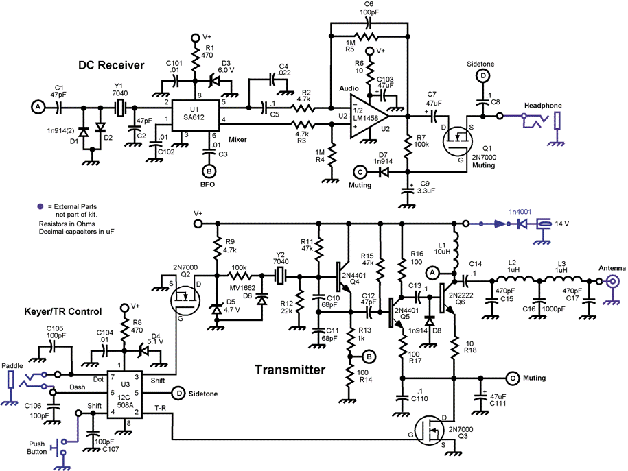
The trick with the Rock-Mite is the PIC (programmable interface controller) which provides keying, RIT and other functions. It is a 12C508 which is pin-compatible to the 12F629 and in a way also to the PICAXE-08M. The main modification would be to write a new firmware for the controller, hence the MEPT/RX would have an onboard beacon keyer.
Option 3 opens this: Use ADC4 (pin 3) for a QRG control via a potentiometer.
The receiver will remain nearly untouched, it already employs a crystal filter and all things needed for grabbing. C1 and C2 however should be replaced by trimmers, so that the filter can be tuned.
With all that said, looking what still is left of the controller, GP0, GP1 and GP3.

When using a PICAXE, GP0 is "out" only. This could be used for RIT control, when using Q2, as indicated above.
GP1 is a digital input and GP3 is an analog/digital input/output. I figure that GP1 could seve as a receive/transmit toggle. Now we are left with one single analog/digital IN/OUT port. What about Johan's idea of including telemetry?
There you have it, the by far best kit to convert to QRSS. BTW: Programming the PICAXE chips is really simple. With a little bit more effort, the 12F629 offers more to play with, in particular more memory.
PICAXE: http://www.rev-ed.co.uk/picaxe/
Check out the schematics:
The Rock-Mite uses a simple oscillator (Q4,Y2) which is pulled (D6) for RIT. Some options here:
- replace the varicap diode by a rectifier or LED and FSK the oscillator with Q1
- leave the RIT alone (allowing for beat offset) and add keying voltage from GP2 (pin 5, PWM!) via some low-pass filter and resistors
- reroute Q2 to GP0 and add extra crystal pulling by using GP2's pseudo DAC (PWM)
Option 3 opens this: Use ADC4 (pin 3) for a QRG control via a potentiometer.
The receiver will remain nearly untouched, it already employs a crystal filter and all things needed for grabbing. C1 and C2 however should be replaced by trimmers, so that the filter can be tuned.
With all that said, looking what still is left of the controller, GP0, GP1 and GP3.
When using a PICAXE, GP0 is "out" only. This could be used for RIT control, when using Q2, as indicated above.
GP1 is a digital input and GP3 is an analog/digital input/output. I figure that GP1 could seve as a receive/transmit toggle. Now we are left with one single analog/digital IN/OUT port. What about Johan's idea of including telemetry?
There you have it, the by far best kit to convert to QRSS. BTW: Programming the PICAXE chips is really simple. With a little bit more effort, the 12F629 offers more to play with, in particular more memory.
PICAXE: http://www.rev-ed.co.uk/picaxe/
Subscribe to:
Posts (Atom)