Saturday, January 4, 2014

2m Magnetic Loop Antenna

Magnetic Loop for the 2m band

Materials and description

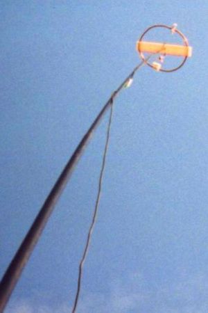
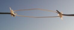
The whole choice is copper. This loop is made of 50cm of 4mm "soft" tubing. The capacitor of  two 1mm circular plates with about 3cm diameter torch-brazed to the loop conductor. The coupling loop is made of 1mm solid wire and held by a luster terminal. Tuning is done by bending the loop to in- or decrease the capacitor plate's distance.
The whole thing is than strapped to a bar of plastics with a tiny whole in it's center of mass to be skewered to my fiberglass telescopic mast. Meanwhile I built a second magnetic loop for this band, made of an old used UHV (ultra high vacuum) ring gasket and a small tube capacitor. The gasket is made of 1mm copper with an outer diameter of 120mm and an inner diameter of 100mm. The capacitor is connected by screws and the coupling loop by a luster terminal screwed on the gasket. A photograph is taken, but not yet available, sri...
The main concern with copper is, that it corrodes. Remember, skin effect... Some finish should be applied to protect the conductor's surface.

Experience

Such kind of omnidirectional antenna gives the possibility to be QRV with horizontal polarisation, as commonly used for the CW and SSB section of the 2m band. This actual design shows a 1.3:1 bandwidth of about 150kHz, centered to 144.200MHz. The SWR on the lower end of the CW section still allows transmitting. The aerial gave good results on the local rag chew at 144.350MHz (using 10W pep) with the clear advantage of the directional diagram of a "lying" magnetic loop.
Do not believe people telling you that this kind of antenna does not work for higher frequencies. It will not make you QRV from the basement, but held up in the air, to the same hight you would lift a beam to, it performs really satisfatory.

Photographs


6m omni-directional antenna

6m omni-directional antenna
(horizontally polarised)


Concept

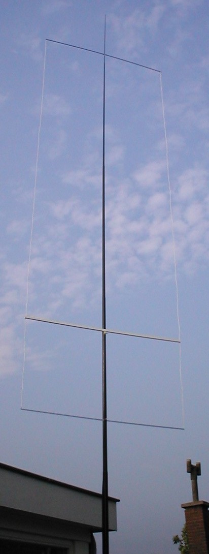
The design follows the idea of the so called "CobWebb-Antenna" for the high frequent shortwave bands. The basic concept of this idea appears to be a folded dipole made of twin-lead  which is then bend in a circle of rectangle. Basically the rectangle seems to be the simpler option.
The folded dipole itself and the way to calculate it's dimentions is well described in the literature, i.e. Rothammel. The idea is to make this dipole from standart twin-lead used for electrical home installations. The remaining problem: What is the velocity-factor of you twin-lead.... I guess you will have to measure it (should not be a big deal when following one of the many articles on that topic).


Dimensions used for 50.15 MHz

Material used:
2 x 0.75 mm²
Total length of twin-lead:
293.2 cm
Length of one dipole leg:
146.6 cm
Distance feed to short:
88 cm

There certainly is some room for optimisations of the dimensions given above... any volunteers?


Photographs

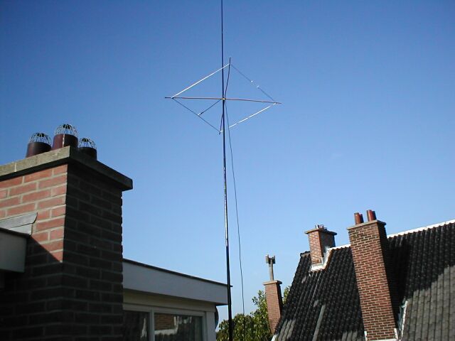
... say more than 1000 words ...


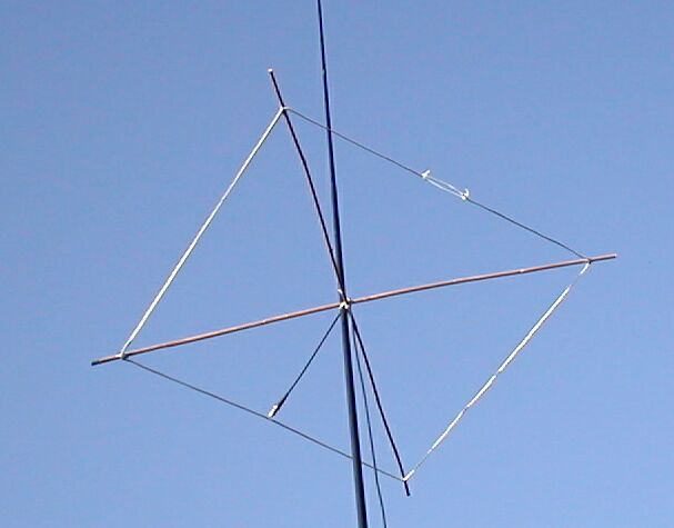
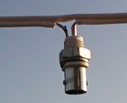
Feeding the aerial using 50Ohms coaxial cable. One of the two leads of the aerial is cut open, the other remains as is (if you are working carefully enough).


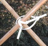
Cable ties to close the loop mechanically, leaving the possibility to apply a little more tension at the very final stage.


For the short-circuit bridges just scratch of the insulation, do not hurt the leads below. I used a little bit of solid copper conductor to join both wires electrically (one twist and a little bit of solder will do too).


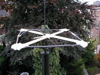
Cable ties again... Here they are forming the all so important cross structure, together with some bamboo poles.
The feeding RG58 and the fibre-glass mast will go through the large looped cable tie.

Next to cable ties and luster terminals I really do like to use duck tape. This way the edges easily attach to the bamboo poles of the supporting cross.


Experience

Smooth SWR about 1:1.1 measured by my IC703. The beacon PI7SIX (JO22nc to JO22eb) tuned in nicely...


My Take on the Rockloop

Rockloop Antenna @dl1gsj


A magnetic loop made just of wire?

Years ago I started experimenting on magnetic loops & Co; I like the idea of narrow resonant aerials. When I saw the rockloop I never believed it might work (Ohmic resistance of the wire). Nowadays, travelling around a lot, I was looking for some antennas fitting my luggage. Again I found W9SCH's rockloop.


rockloop sketch


Thoughts to the original design

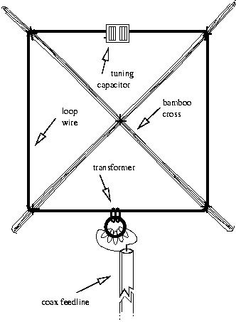
If I interpreted the original design correctly, the rockloop is constructed of a radiator wire, a transformer and a tuning capacitor. The transformer, as implied in  G3YCC's description , seems to be made of a different (at least another) wire than the radiator. Following the calculations that can be done on magnetic loop antennas, one knows about the extremely low radiation resistance of these loops. This requires the total Ohmic resistances to be as low as possible. To gain the lowest possible Ohmic resistance, I decided to use a larger dimensioned toroid core to fit five windings of the radiator wire on it (no solder joints, lower losses).
 

Materials

  • about 4m insulated copper wire 
  • 2 bamboo pole 1.2m long
  • toroid core of your choice
  • variable capacitor
  • bunch of cable ties
  • insulated wire for the primary transformer winding
  • BNC connector or coax cable (or both...)

Dimensions
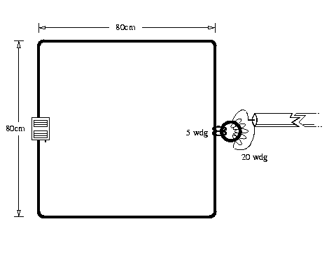

 sketch w/ dimensions
The four sides should have a length of 80cm, this will enable you to resonate the antenna up to the 15m band. If there are needs for the higher bands one should go for shorter sides. The transformation ratio was suggested by W9SCH. The 5 windings on the secondary side will influence the overall inductance of the loop...


Transformer

Everything is said already. Just have a look at the photograph. I have to admit, there certainly are better  ways to mount the BNC connector...
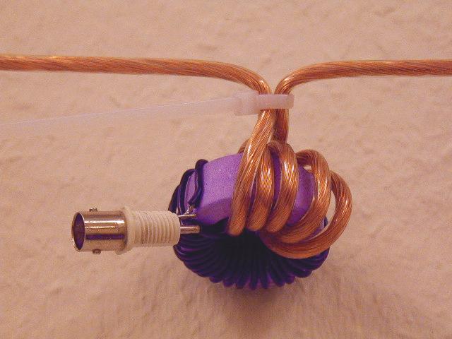
transformer


Tuning Capacitor

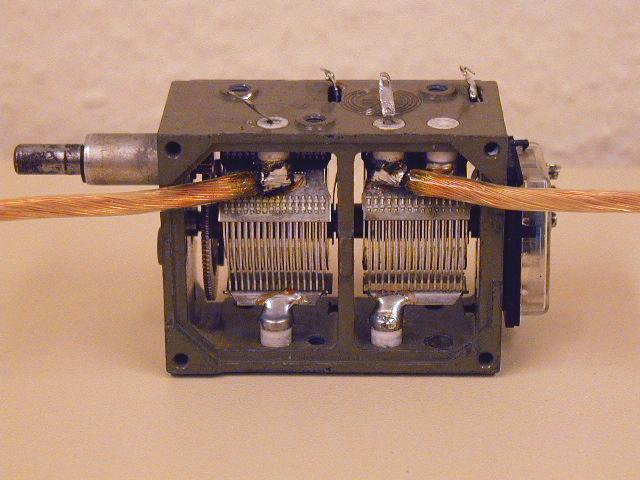
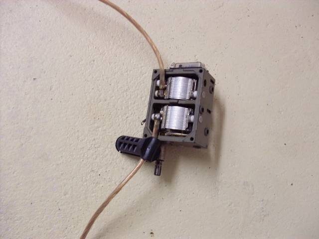
We are going QRP with this aerial anyhow. I found this one in a old BC-RX (my favourite source for these things). It helps if the capacitor has two identical sections. Feeding just the stators will on one hand leave the rotator and therefor the chassis w/o RF on the other it double the voltage rating. The solder joints should be as solid as possible (remember the resistance story). I used a 80W iron to solder the loop wire directly to the stators.


Overall View

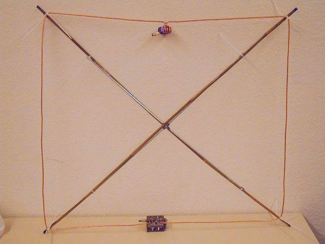
Showing pictures, it might be reasonable to show the whole thing. What I found helped, so there ist a  shelf's backside steelcross used to give support for the bamboo rods. This will disappear soon... making place for some more cable ties. Please excuse the poor light quality on this one, was made on a business trip in the middle of the night.

rockloop photograph


Experience

The tuning range is huge.  I observe resonance between 5 and 22MHz.  Even though it tunes on the 40m band, I believe transmitting there might not make that much sense - radiation efficiency would not be that great. I used the lower range to listen to broadcast.
First QSO on 20m during this business trip (Germany) resulted in a report of 579 from Hungary using 2W PSK31 (w/ FT817). At this time the antenna was hanging on a wardrobe (indoors, as you expect). The room was located at the ground floor of a steelwork office building.


Some news on my rockloop

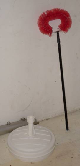
I went out for some shopping, and that's the result (well, not the Al-boom on the floor):

2009 purchase

These things can be turned into something useful for the rockloop. Up to now I had it hanging off stuff like curtain rails etc. This, however, is not a real solution, in particular since sometimes, it is really difficult to find a mounting point not too close to walls.
Thus, here's a very very cheap and easy solution. The sunshade stand cost me less than 4 Euros, the spider web broom was about 4 Euros.
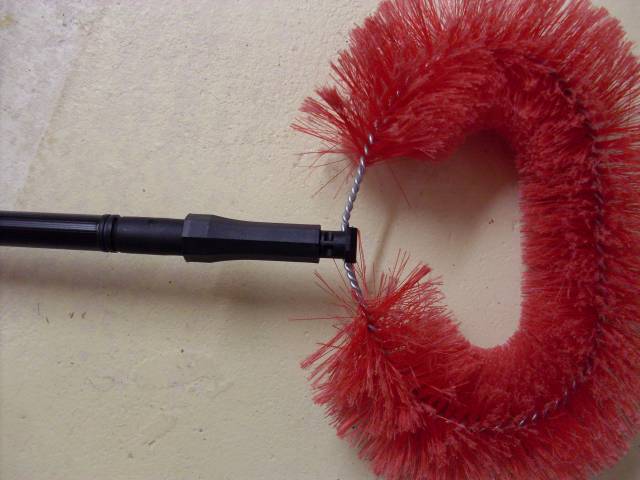
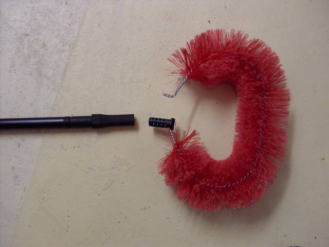
Let's see what the mod is like. The broom itself can be easily separated from it's telescopic stick. Simply pull (carfully) on the steel bits. Twisting the stick slightely helps a lot. The result would be something like this:

separating
separating

The top plastic bit actually does all the trick for us. However, there was some material connecting both legs on the inside part, that needs to be cut off. This modified bit perfectly fits my loop wire. Like this:

loop1

Next step, insert the broomstick into the sunshade stand. I skipped shooting a photograph of that respective step...
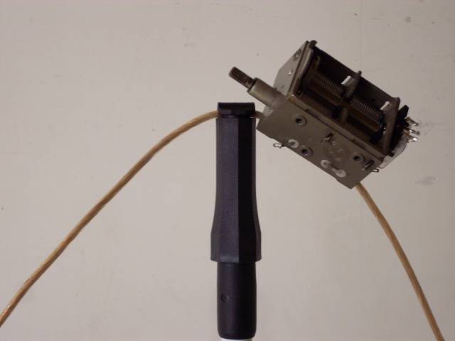
In the sequence of events, the plastic bit will mysteriously find it's way back home into the business end of the broomstick. As such:

bit back home

And the final result, as set up in my garage:
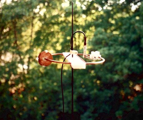
rockloop on broomstick


Hentenna for the Magic Band

Hentenna for the 6m band


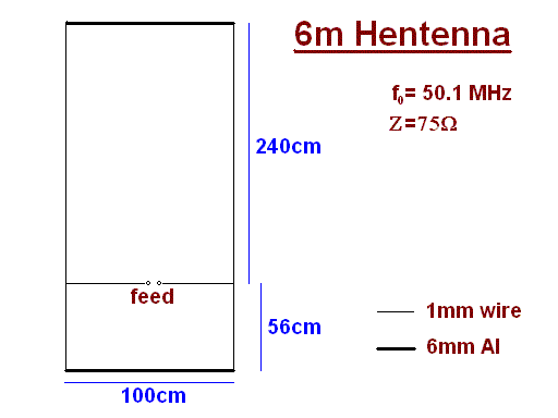
Dimensions


hentenna sketch

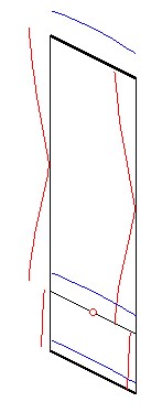
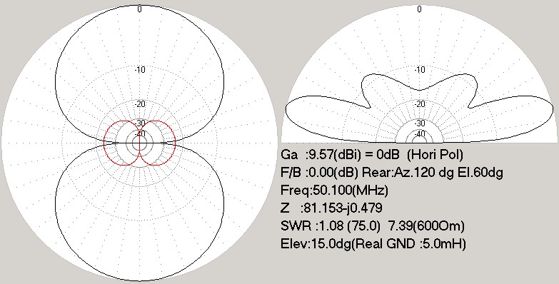
Simulation using mmana

First image showing the current distribution on the aerial, the second one the directional diagrams. The "real" ground settings were used, with the Hentenna "placed" in a hight of  about 5m.


directional diagrams

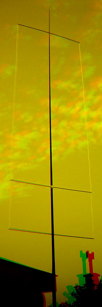
Normal and 3d photograph

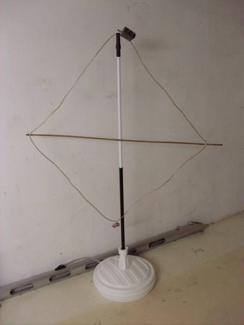
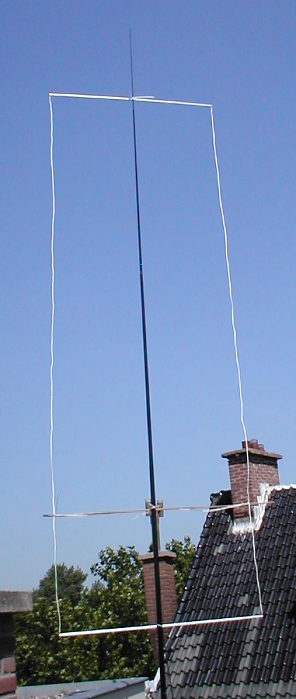
This is what it finally looks like...
photograph


If you happen to own red/green glasses for viewing 3d-images:

Hints & Experiences

The feeding section perfectly fits into a small (13x13mm²) 1m long cable channel. The cable channel suffers from a couple of holes drilled in it's sidewall in order to guide out the feeding leads. A luster terminal is finally applied to connect the coax cable. In a former version a bamboo pole was used; doesn't look as nice, but less work to be done...

You might practice some inventiveness in order to connect the 1mm cables to the end of the aluminium poles... I squeezed the end of the pole a little bit with pliers and cut a 4mm thread into the inner surface of the Al pipe.

Used it as shown above. The aerial gave nice instantanious results (beacons & Co.), even though that the band was pretty dead, I managed to have some QSOs with reasonable results. My impression is, that the Hentenna performs better than my commercial Al-pipe dipole. Moreover it is easier to transport and/or store anyway.
The total costs were about €10.- w/o the feeding RG58 --- I known, 50Ohm cable to a 75Ohms aerial...

2m omni-directional horizontally polarized antenna

2m omni-directional antenna
(Squarooka - squared bazooka)


Concept

Sort of similar to the one of the 6m omni. Instead of using twin-lead, this design makes use of a more or less regular double bazooka antenna (coaxial dipole). Your attention shall be drawn to the available standart literature, such as Rothammel.
In order to "compute" the dimension, Karl Rothammel mentioned that the total length of the dipole shall be 95% of the free-space wavelength. The short-circuit bridges (closing the folded dipole) are to be placed at a distance-fraction being equal to the velocity factor of the coax cable used, which will be 66% using RG-58 or RG174.


Some Simulations....

No sofisticated simulations have been done on this aerial... Just to give a short impression what can be expected, a very rough simulation using "real" ground setting with an antenna height of 9.5m (corresponds to a height gained by a DK9SQ "fibreglass telescope tower").


the horizontal directional diagramm


and for completeness, the vertical diagram too


Dimensions used for 144.350 MHz

Material used:
RG - 58 C/U
Total length RG58:
98.6 cm
Length of one dipole leg:
49.3 cm
Distance feed to short:
32.5 cm

Based on a free-space wavelength of:
( 299.79 / 144.35 ) m = 2.0768 m


Have a closer look

... and identify my favourite materials. The cross is made of some strange PVC profile this time. You might also recognise one short-circuit bridge on the front right of the square.


Construction

The difficult part in building a double bazooka antenna is cutting the coax. More precisely: NOT cutting throught vital parts of the coax cable, i.e. the braid.
As shown in the image below, the outer (black) insulation and the shield have to be cut, preferably w/o cutting into the dielectric...


This is the way I usually do these sort things:     
  • scarsify the insulation with a sharp knife at the first side of the feed point, taking care not to cut through the black polymer
  • bend the cable at the cut, which will cause the insulation to torn apart precisely at the cut
  • scarsify the insulation with a sharp knife at the second side of the feed point
  • cut in a straight line from the first to the second edge and peel off the insulation
  • wind one turn of 1mm solid copper wire (approximately 1cm long) around the shield on each side of the feed region adjacent to the outer insulation
  • twist the ends of the copper wires with pliers in order to firmely press the shield onto the dielectric
  • cut the shield in the middle of the feeding section, taking care not to cut into the dielectric
  • bend the shielding portions over the copper winding
  • solder shields and copper winding together
  • make sure that no filament of the shield remains between the two feed points
  • ouffff!!!!!
Next critical point: the short-circuit  bridges. A photograph of the finished product would be useless... and... I did not take any when tinkering things together....
Here is the way to proceed:
  • take a knife and cut the insulation and the shield of the coax cable precisely at the position of the bridge, this time taking care to cut the dielectric too by leaving the braid unhurt (may not cutting the dielectric completely down, but leaving a little bit uncut)
  • bend over the coax cable at the cut as far as possible, this will lay open the braid and hopefully tear the remaining dielectric apart (if the last did not occur, whittle the last layer of dielectric away)
  • here comes the copper wire again, push some below the braid (might be tricky) and bend it over the braid - this will make the short-circuit between shield and braid
  • carve some insulation off the rims of the cut
  • solder the braid to the copper wire
  • bend back the coax into a straight line
  • solder the copper wire to the shield, both rims must have good contact
  • tataaaa!!
Go on with the remaining task building a cross, etc. BTW: You will need 35cm poles, building a square of 25 x 25 cm². Cable ties ... ... ...

I used duck tape to fix all together, including the joint of the dipole legs opposite the feed point (visible on the above photograph). Looks ugly, builds quickly.... good luck!


Experience

It was built just the day before this text came to see the cyber-world's light... therefore there was no time at all to do more than just an RX check-up. PI7CIS (JO22dc) tuned loudely in my Belcom LS-202E (which is not really surprising, since the beacon is just a couple of kilometers apart from my place in JO22eb). By turning the mast around a slight volume change could be heard, even though the S-meter reading did not really change.
Second rx-test (13.Sept.2003), with the FT817 this time, gave S8 on PI7CIS and S1 on GB3VHF (JO01dh)  and PI7PRO (JO22nc). Besides the beacons the band was quiet.... therefore still no tx-test.


80m Frame Antenna

I published the design of this antenna years ago. At a low power experiment, it was able to convey a 20mW QRSS signal, mounted indoors, from Holland to the UK. Thanks Colin G6AVK for this particular experiment!

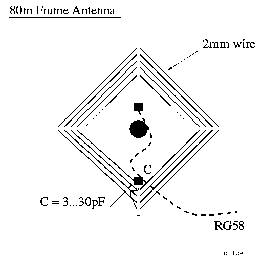
80m Frame Antenna

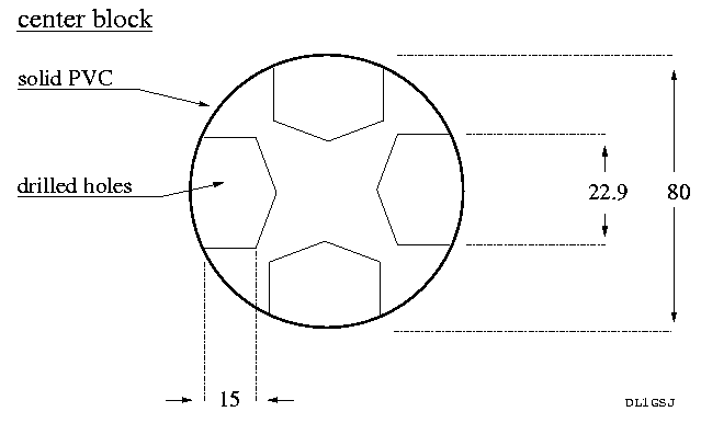
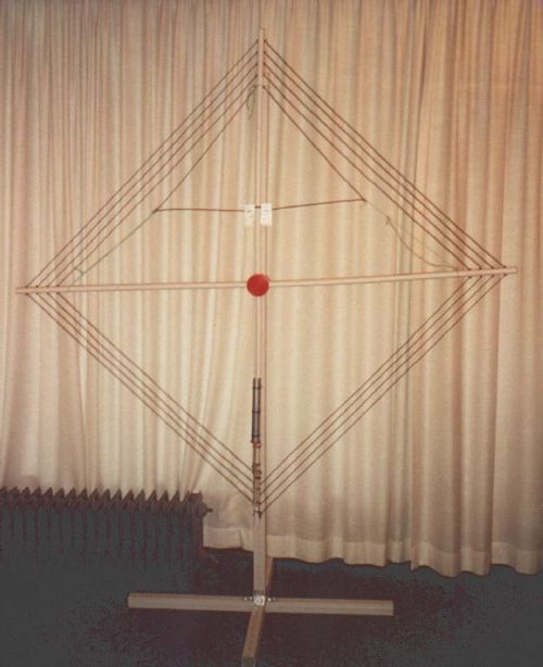
This frame antenna was intended to be as easy as possible to build, mount and dismount. It was thought to travel around in my luggage on flights. It is built of 90cm long poles and a block in the centre. The cross will be held together by the tension of the wire. Therefore the wire should be fixed on every single guide. Small cable ties will do a great job.

What you need:

  • 3.6m round PVC installation tubing

  • (22.9mm dia for stability)
  • approx. 20m wire (2mm dia)
  • solid PVC block
  • 42 cable ties
  • nylon thread (to fix the coupling loop)
  • capacitor 3..30pF (plate spacing > 2mm)

  • alternatively I built a tube capacitor (*)

Building the frame

Cut the tubing into 900mm long pipes and drill 5 wire guides 3mm dia through it (see drawing). Machine the centre block as shown in the sketch. You will have now a good chance to see if the mechanical part was done appropriately. Wire pulling... I used 2mm coated wire (give 2.8mm diameter). Hint: start somewhere in the middle.

The coupling loop

The coupling loop is something that strongly depends on the environment. You should experiment on that a bit on your own. A crossneadle SWR-meter really helps ;-)

Capacitor

Be careful with the mounting of the var cap and it's handling. Voltages really get high over there. It is easy to get a neon bulb glowing at 10W RF injected at resonance. A BBQ motor could be a great help for tuning the device... For QRP use, the frame might be placed in the shack (hotel room), ensure enough insulation !!! There really is danger to life.
(*) An aluminum pipe, a threaded rod and a plastic distance washer will give a HV proove and fine tuneable capacitor. Disadvantage: not remotely tuneable. Again: Never touch any portion of the cap whilst applying RF to the antenna!

Properties

The natural resonance (open loop w/o capacitor) is around 4.6MHz. The var cap will bring that to a range of 3 to 4MHz. The measured bandwidth at SWR 1.1:1 is about 10kHz. The antenna can easily be dismounted and transported in a small bag. It will take you a while (at the beginning) to disentangle the wire. With some practice you will find it easy to remount the frame within 5 minutes. All distances are kept by the cable ties, all you need is to stick the poles in the centre block, in the correct order.

Tripod

Two 2m pieces of 40mm x 40mm PVC cable channel make a wonderfull tripod. Cut one into two one meter long pieces, cut out appropriate edges in the middle of those (keeping the backbone untouched!) and build a cross - this will be the "foot". The "mast" will be made of the second cable channel. Use 4 steel angles to mount the mast to the foot. Cable channel has the advantage of wholes in the backbone, easy way to adjust the height of your frame to what you need/have inside/outside your shack. Besides that it's not known to have any severe influence on coils or capacitors... ;-)

Caution!

I will not sign responsible for any damage produced with this design! There are risks, and you are warned. Be intelligent!

Drawings

Frame antenna outline
Pole detail sketch

Center block design


Photographs

The whole frame mounted on it's tripod
 
whole frame

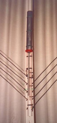
Detail view of the capacitor section. RG213 inner wires with insulation are visible, they are used to tune the range. Also on the picture the cable ties keeping the wire in the proper position.
capactior section


Subharmonic 30m RX Design

30m QRSS Grabber Receiver


The basic design is a mix of ideas gathered from pa2ohh, the ARRL Handbook and publications made about the subharmonic mixer of Prof. Polyakov (ra3aae).
Since I am a really lazy dawg, thinking came first...

What we want to observe is 10140000 to 10140100Hz. Let's see what is available.... 10.140MHz crystals, close, but too close for comfort. Pull those crystals, and oscillators will become less stable. 10.125MHz crystals... too far off! 10.135MHz, closer, possible, but still pretty far off; 5kHz, oh my goodness!

But we also got really cheap and well available crystals and oscillators (!) at 5.0688MHz. Multiply by two and we are at 10.1376MHz, that's just 2.4kHz off the lowest frequency we want to receive. 2400-2500Hz also is in the comfort zone of any random soundcard at even low sampling rate.
To use this particular frequency, all we need to do is, multiply by two, or in other words, double it.

Jan (pa9qv/oz9qv) pointed me towards Prof. Polyakov's mixer, also known as the Russian mixer. Great readings from late la8ak, check this out: http://noding.com/la8ak/c21.htm

Thus, there we are, ultra-cheap 5.0688MHz CMOS-oscillators combined with a Russian mixer receives the 30m-qrss-band at about 2.4kHz. Let's design something!


Final design

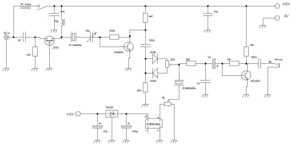
A Polyakov mixer is supposed to work best with a sine signal. The CMOS-oscillator's signal however looks more like a squarewave, involving a lot of harmonics. The easiest and cheapest way, as it seemed to me, to transform that into a sine, is a crystal in series resonance.

The unwanted lower sideband has been taken care of by including a 10.140MHz-crystal behind the preamp.
Behind the filter, a RF-amp is added to compensate for losses. Due to this, the filter response is now shifted up again, I will look into this, but for now, I will let the receiver run and collect data/info.
As promised, I looked into it, shifting a crystal up is done by capacitive load. Reducing this load will bring the crystal closer to its series resonance frequency. To be a little bit on the adjustable side this time, I added a trimmer found in my junk box. I thought it would have a max. capacity of 18pF. This trimmer allows for adjustment of the crystal filter pass band frequency.

Consideration for operations w/o the filter: we are looking at a bandwidth of 100Hz and the received LSB will be (about) 10135100Hz to 10135200Hz. I figure, there is just the occasional Feldhell QSO, but other than that, the LSB range of the DSB receiver seems to be an empty spot.

A jumper is added in order to enable support of an active antenna via coax cable. The ideas for an active aerial are floating presently. It will be a shielded resonant loop with a preamp, that's for sure. The loop will be made from "YMVK-as 2x2.5mm²" which is underground twin-lead mains cable, doubly shielded. In an earlier experiment I successfully made a 40m-75m RX-loop from that stuff.

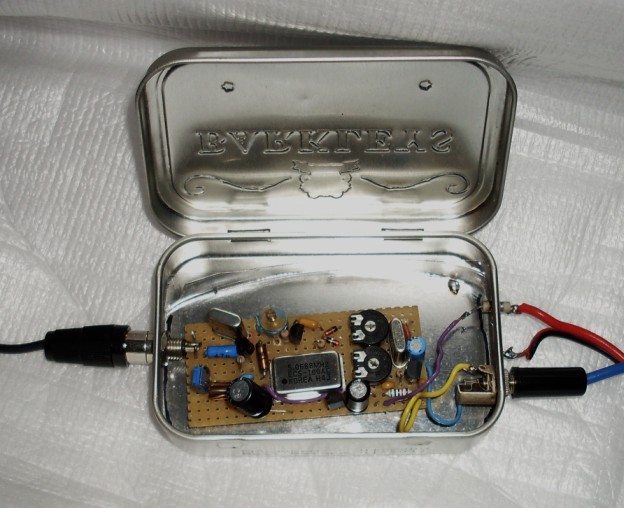
Subharmonic 30m direct-conversion receiver
 

Photo of the 30m direct conversion receiver


The actual receiver, as running for many years

Monday, December 9, 2013

How to tune the suburban sub-harmonic receiver


Some help to adjust the balance and drive of the sub-harmonic receiver used in my grabber (dashed lines indicate 0.7V cut-in voltage for Si-diodes, V is mixer drive voltage).

1) Mixer correctly driven: Within one period a single diode opens for exactly 90 degrees (red). Within the same period, the other diode opens for 90 degrees (blue), while the rest of the time, the diodes are both closed (yellow). As you see, the first diode opens at 45 degrees, that is very important! You also see, the entire mixer is open twice within one period; that’s the trick of the frequency doubling. Any off-balance shift will produce harmonics, which you can’t get rid of.


2) Let’s have a look at the mixer being extremely out of balance. In this example, -0.7V, which would open the second diode, is never reached, hence, this diode will never open. Consequently, the mixer will open once in a period, thereby not doubling the frequency. Still, due to under-sampling, some signal will be received, however, this is essentially a DC-RX for the LO-frequency. Actually, one can make use of this, e.g. for a 14MHz sub-harmonic receiver, which, when adding the correct off-set, will turn into a 7MHz DC-RX (either with a second crystal filter, or non at all).

3) And now, the mixer in balance, but over-driven. This will let a lot of signal through and will actually also double the frequency. However, the phase of the mixer is now totally off, i.e. asymmetric. This will produce a lot harmonics, so the receiver will receiver on many multiples of the local oscillator.


Actually, it takes a bit of patience to find the sweet spot in such a receiver. For me, it works well, for many years by now.

Saturday, October 26, 2013

QSO?

What is a QSO nowadays? Not sure, in particular when talking QRSS.

The latest fashion seems to communicate via an online grabber. This this a QSO?
I don't think so, for the following reasons:
  1. both stations have contact to the grabber, which is rather an automated SWL connected to the internet
  2. there is no wireless link from the online grabber to neither of the two stations
  3. the online grabber does not repeat a signal per se
However, all in all, I believe using a grabber to communicate is somewhat fun, since the communication is somewhat full-duplex.

What amateur radio is concerned, there still is the issue of dependency of many non-amateur communication channels, namely the ISPs of the three involved parties.

Friday, October 18, 2013

Small Wonder Labs closed

Today I learned that Dave K1SWL closed his QRP business for good. Very understandably, after many years of excellent service.

I would like to thank Dave for all the inspiration he brought to the QRP community over the decades and wish him a good time in the house he built in NH!

72 es 73