By chance I came across another web-page sharing very useful information about the material, in particular when used for radio.
Have a look:
http://sivantoledotech.wordpress.com/2010/09/03/hello-world/
http://sivantoledotech.wordpress.com/category/radio/antennas/page/2
http://sivantoledotech.wordpress.com/2010/09/18/a-tuned-active-receiving-loop/
http://sivantoledotech.wordpress.com/2011/05/10/the-trombone-magnetic-loop-for-50mhz/
Friday, February 14, 2014
Saturday, February 1, 2014
PE-Xc/Al/PE-Xc aka PEx/Al/PEx the New Copper?
Wanting to build a low profile mono-band antenna, I looked into the old design by J.M. Boyer (U.S. Patent 3,151,328). The DDRR-antenna, as originally designed, i.e. about a quarter wave circumference, allegedly as a rather narrow bandwidth.
There is another variant out there, which is said to got a wider bandwidth. This design asks for a half wave circumference, which the advantage of having a closed loop (less noise!) and no need for an expensive capacitor.
OK, that's a plan, let's think of a DDRR for my flat root top. This antenna would be entirely invisible from the street.
But, what about the B.o.M. (Bill of Materials)? Well, a neat design would call for about 21.34m of soft copper tubing having a 10mm diameter. Well, the stuff exists, however, however, a 25m roll of 12mm soft copper tubing would cost about €185.- presently. Well... that's a bit too stiff or my taste!
The hardware store had also 5m rolls of 12mm copper tubing for about €30.
OK, we are coming closer, I would need to buy 2 such rolls and an additional piece of piping, in order to build a quarter wave DDRR antenna. But, I would need to think of a (variable) capacitor.
Nothing of interest, I decided, and left this particular store.
Next store, maybe their copper prices are lower... no, there were not! However, I noticed some other stuff, which the first store did not sell. The stuff is called PE-Xc/Al/PE-Xc, aka PEx/Al/PEx.
What is that?!
Well, there is this other material in the and ....
Right, now we know that the PEx/Al/PEx stuff can be interesting for building antennae.
Also good to know, the stuff is very lightweight, compared to Copper tubing. Not only is Aluminium one of the lighter materials, the Poly-Ethylene makes the stuff really tough (10bar of pressure at 95C), such that the metal layer can be much thinner. Mind you, in radio frequency, we are only interested in the most outer diameter of the metal, thanks to the skin-effect.
The price? Alright, time to talk money. I bought a 10m roll of 14mm PEx/Al/PEx for just under €30. Only half the price of Cu-tubing?! Is that worth it? Well, the costs are not hidden in the materials for PEx/Al/PEx, since, a 10m roll of 20mm tubing, the largest diameter this particular store had in stick, is only €35.
Enough about the material itself, you'll find plenty of information about it on the interweb!
A material so light-weight and still stiff calls for designs like hair-needle antennae and alike.
Pretty novel, I thought... NO it is not! There is one design disclosed in the interweb, which makes use of PEx/Al/PEx in a magnetic loop / frame antenna cross-over. Have a look at the "2 TURN LOOP ANTENNA".
What I like about this design is that no electrical connection is made to the Aluminium layer. Why? Aluminium is not exactly a noble metal. Any connection with a metal other than Aluminium may cause problems, one or the other way.
Along those lines, how would one possible connect a capacitor to the Al-layer? Well, that is, considered the dimensions, actually pretty simple. Have a look at the images below, they may look disturbing. And yes, this is pretty ghetto!
And here is where the capacitor resides, between the Al-layer of the PEx-Al tubing and the braid of the RG-213. Of course, the braid of the 213 is made from Copper, however, the is no Galvanic connection between those metals, and hence, no corrosion!
Although the RG-213 fits into the PEx-Al tubing nicely, there is some friction... and that is good!
Ideas
First, I had in mind building a DDRR-antenna. However, seen the possible simplicity, I may build a magnetic loop first.
Post Scriptum
It seems that the PE-Xc/Al/PE-Xc, best suitable for amateur radio, is found under "floor heating".
There is another variant out there, which is said to got a wider bandwidth. This design asks for a half wave circumference, which the advantage of having a closed loop (less noise!) and no need for an expensive capacitor.
OK, that's a plan, let's think of a DDRR for my flat root top. This antenna would be entirely invisible from the street.
But, what about the B.o.M. (Bill of Materials)? Well, a neat design would call for about 21.34m of soft copper tubing having a 10mm diameter. Well, the stuff exists, however, however, a 25m roll of 12mm soft copper tubing would cost about €185.- presently. Well... that's a bit too stiff or my taste!
The hardware store had also 5m rolls of 12mm copper tubing for about €30.
OK, we are coming closer, I would need to buy 2 such rolls and an additional piece of piping, in order to build a quarter wave DDRR antenna. But, I would need to think of a (variable) capacitor.
Nothing of interest, I decided, and left this particular store.
Next store, maybe their copper prices are lower... no, there were not! However, I noticed some other stuff, which the first store did not sell. The stuff is called PE-Xc/Al/PE-Xc, aka PEx/Al/PEx.
What is that?!
- PE-Xc or PEx stands for "cross-linked Poly-Ethylene"
Well, there is this other material in the and ....
- Al stands for Aluminium (Aluminum)
 |
| 14mm PE-Xc/Al/PE-Xc |
Also good to know, the stuff is very lightweight, compared to Copper tubing. Not only is Aluminium one of the lighter materials, the Poly-Ethylene makes the stuff really tough (10bar of pressure at 95C), such that the metal layer can be much thinner. Mind you, in radio frequency, we are only interested in the most outer diameter of the metal, thanks to the skin-effect.
The price? Alright, time to talk money. I bought a 10m roll of 14mm PEx/Al/PEx for just under €30. Only half the price of Cu-tubing?! Is that worth it? Well, the costs are not hidden in the materials for PEx/Al/PEx, since, a 10m roll of 20mm tubing, the largest diameter this particular store had in stick, is only €35.
Enough about the material itself, you'll find plenty of information about it on the interweb!
A material so light-weight and still stiff calls for designs like hair-needle antennae and alike.
Pretty novel, I thought... NO it is not! There is one design disclosed in the interweb, which makes use of PEx/Al/PEx in a magnetic loop / frame antenna cross-over. Have a look at the "2 TURN LOOP ANTENNA".
What I like about this design is that no electrical connection is made to the Aluminium layer. Why? Aluminium is not exactly a noble metal. Any connection with a metal other than Aluminium may cause problems, one or the other way.
Along those lines, how would one possible connect a capacitor to the Al-layer? Well, that is, considered the dimensions, actually pretty simple. Have a look at the images below, they may look disturbing. And yes, this is pretty ghetto!
 |
| RG-213 meats PE-Xc/Al/PE-Xc |
 |
| close up |
Although the RG-213 fits into the PEx-Al tubing nicely, there is some friction... and that is good!
Ideas
- Building a magnetic loop from the materials shown above.
A single turn loop made from PEx-Al with a length of RG-213 inserted into both ends of the loop symmetrically. The loop will be tuned by widen or closing it other the inserted length of RG-213, actually acting like a butterfly-capacitor. I will aim for about 14.070MHz. Once tuned, I will tape up the loop endings in order to lock tuning and prevent moisture to enter into the tubing. - Building a quarter wave DDRR, as intended in the first place.
Similarly to the magnetic loop above, the capacitor will be formed by RG-213 inserted into the PEx/Al tubing. However, there is a problem with the ground connection of the loop! The present idea is to remove the outer PE layer, wrap the Al-layer with Al-foil and clamp this down with a hose clamp. Of course, the Al-foil will corrode, hence, it will have to be replace occasionally. - Building a frame antenna.
This essentially means to coil up a good part of the PEx/Al to a decent pack, having a coupling toroid in the center winding. This technique, you might have seen at various antennae I published before, e.g. OctaPlumb (different plumbing material though). - Different PEx/Al tubings might fit into one-another, forming capacitive couplings.
- I can imagine using PEx/Al with INOX-screws connecting various coils thereby, together with capacitors as disclosed above, forming traps.
- The PEx/Al tubing might potentially be usable for shielding a loop made from RG-213. Insert theRG-213 into the tubing, both end peaking out. Solder things down at the "far end" of the loop and slide the far end to the tubing... Follow your imagination for the rest!
First, I had in mind building a DDRR-antenna. However, seen the possible simplicity, I may build a magnetic loop first.
Post Scriptum
It seems that the PE-Xc/Al/PE-Xc, best suitable for amateur radio, is found under "floor heating".
Wednesday, January 29, 2014
Update: Flower Pot Heater
The last few days, I experimented a bit with the flower pot heater... actually, I turned the one heater into two! All experiments were done whilst my central heating was set to "frost protection".
From a physics point of view, the 4 pots, as shown in the previous post, are a rather large thermal mass. And of course, physics does not lie. Despite the 4 candles, it took some time to build up noticeable radiant heat, which than lasted for quite a while. In this respect, the 4 pot solution is more of a constant heater than an "on demand" device.
At some stage, I removed one inner pot and tried with 3 pots bolted together. This has proven to be a little bit faster in heating up, satisfactory it was not. The mass of the big pot takes too long to warm up appearently.
The next experiment was to use the second to largest pot and the 2 smaller ones. I also removed the brick at the opposite end, since I noticed that the candles were not getting enough oxygen. Well, some improvement, but still not really up to scratch.
In the next iteration of experiments, I used only 2 pots, the smallest and the second to largest. Also, I reduced the amount of metal inside by using a shorter bolt. The reduced circumference of the setup allows for a smaller soucer to hold the candles. The bricks set flat now, the distance between the flame(s) and the thermal mass is reduced, speeding up the warm-up. Noticeable difference!
Some remark here, it seems that in particular when using more than 2 tealight candles, the soucer I used was filled up with cold CO2 so quickly that one candle always fainted. It seem that the heat-transfer is very effective, so effective that the CO2 fall straight down on the candle(s). When the setup is warmed up a bit, this effect is gone.
Radiant heat is kinda cool (warm that is), however, what about heating air? And yes, this works well, however, it slows down everything again. What works well, you may ask...
I used 4 candles in the 2 pot heater mentioned above and placed the big flower pot on top. Since this time the big pot is not connected to the bolt, the hole in the pot is open. Heat builds up between the bolted 2 pot setup and the outer loose pot, which due to the chimney effect is drawn upwards through the big pots hole. In the course of time, also the big pot heats up such that it radiates heat.
Such a setup creates heat by convection and at some later stage also radiant heat.
Latest experiment: two 2 pot heaters.
I believe you understand where I am going from here. The big pot was loose already, and the second to smallest was not used at all.
Some considerations about the 2 heaters I have presently available. The biggest pot will have a large thermal mass, which stores heat for a while. The smaller pots (less mass) will heat up fast and start radiating relatively quickly.
Since a couple of days I experimented successfully with the following scenario. The smaller heater is in my study, where I do stuff in the late afternoon, just when I returned to home. This room needs quick heating, so I use the smaller FP-heater with 2 or 3 TL-candles, to get radiant heating asap. At the same time, I would light a single TL-candle in the big pot heater to create a certain baseline warmth in my bedroom. Halfways into the evening/night, I might have to replace this single TL-candle with a fresh one. The big pot does not get very, it is warm to the touch at the top and cold at the lower side, however, my bedroom feels just right with this amount of heating.
Again, this is not radio related... sorry for that! However, I believe that this could be of some interest to some of my audience.
2 tealight candles per night to keep your bedroom comfortable... how cool (ergh warm) is that?!
BTW: There are some critics writing rather negatively about this particular way of warming a room. And honestly said, they have point!
We, including me, are talking about "heaters". Of course this evokes the impression that those things are really hot, creating a lot of "heat", litereally. But than, those devices are not up to such expecations for very simple reasons. Here is one: tealight candles are designed to keep a pot a tea warm for some while... that's all! The idea is not to create an amount of heat so that the tea will evaporate in a couple of minutes. So, should we expect the very same candle to be as hot as a Bunsen-burner?! It is the constant flow of a small amount of energy that keeps your bedroom cosy... not more than that!
Saturday, January 18, 2014
The E-Probe Got a New Location
The regular reader of this blog may know, that I am using different aerials for my grabber. All on a longer term. First it was the DCTL, than it was the E-probe (aka. modified mini-whip).
For many months, the E-probe was just dangling from the edge of my upper roof, which screened South by a good part.
Since some weeks, I put it on my upper roof. As soon as it was up, of course we had a solar storm and condx went down. Even with condx up again, not a single DX was received. I figure this would be caused by the rather low position of the E-probe. Reason for that decision was to be safe in storm. It can actually blow a bit here in South Holland.
Here is how this setup looked:
Today, I decided to raise the E-probe by 1m, by adding an additional piece of PVC pipe to the construction. Originally, I wanted to use a straight coupling piece to do that, but that would have meant to pay a visit to the hardware store. In garage, where I kept the piping, I found a matching T-coupler. This could be used to the advantage of the setup!
Why not feeding the coax-cable through the stand, a guide it out at the T-coupler?
Of course, first I had to take thing apart, in order to feed the coax through the stand's tubing.
Now to the first impressions. Of course I did not shutdown the grabber during the process, so one can see a clear "before and after" (and also some in-between).
What happend? (times in Zulu/UTC)
I just hope that the leverage of the higher E-probe will not cause the entire thing to be blown off the roof by the next breeze.
Update:
The relatively lightweight bricks are now replaced by heavy concrete garden tiles. This should do, even when storms should come up.
The bricks will now be used for another flower pot heater...
For many months, the E-probe was just dangling from the edge of my upper roof, which screened South by a good part.
Since some weeks, I put it on my upper roof. As soon as it was up, of course we had a solar storm and condx went down. Even with condx up again, not a single DX was received. I figure this would be caused by the rather low position of the E-probe. Reason for that decision was to be safe in storm. It can actually blow a bit here in South Holland.
Here is how this setup looked:
 |
| E-probe, just above the edges of the roof |
Today, I decided to raise the E-probe by 1m, by adding an additional piece of PVC pipe to the construction. Originally, I wanted to use a straight coupling piece to do that, but that would have meant to pay a visit to the hardware store. In garage, where I kept the piping, I found a matching T-coupler. This could be used to the advantage of the setup!
Why not feeding the coax-cable through the stand, a guide it out at the T-coupler?
Of course, first I had to take thing apart, in order to feed the coax through the stand's tubing.
 | |
| Disconnected and in pieces |
 | |
| DONE! |
 | |
| Before |
 |
| During (and after) |
 | |
| After |
- 13:26 - I disconnected the coax from the E-probe
- 13:30 - reconnected the coax and arranged stuff
- 13:33 to 13:34 - cleaning of the BNC-connector
- 13:34 - I left the roof
I just hope that the leverage of the higher E-probe will not cause the entire thing to be blown off the roof by the next breeze.
Update:
The relatively lightweight bricks are now replaced by heavy concrete garden tiles. This should do, even when storms should come up.
The bricks will now be used for another flower pot heater...
Friday, January 10, 2014
How to Create IR Radiation on the Cheap
Before you continue reading, this is entirely off-topic, really! You might have heard about the hype of "flower pot heaters", which is all over the internet, in particular youtube. Well, this is my attempt on building one.
Usually, when a candle burns, the hot combustion products just go up to the ceiling, where the heat is than disposed. Very useful indeed.
If you have ever been to a room full of candles, you will certainly remember that such a room get quite hot after a while. If you have never experienced this, there is a nice scene in the German comedy movie "Rossini".
The basic idea of the "flower pot heater" is to catch and store the heat of (a) candle(s) in a thermal mass. The problem with candle exhaust is of course that it goes straight up, to catch it, one needs some cloche shaped thermal mass.
Of course, at some stage, hot gases will have filled the cloche. At that stage, said gases will spill over and reach for the ceiling, which is undesirable (see above).
So, lets put a larger cloche above the first one, and than another, and another, and another ..... well, we have to stop somewhere.
I went for 4 raw terracotta flower pots. Terracotta is a pretty nice material, since it is rather heat resistant having been burnt before (terra cotta = baked earth). There are glazed pots available, avoid those, the glazing will reflect IR radiation rather than absorbing it. Yes, we also want the IR and vis. radiation of the burning candle(s).
The pots, cascaded as a matryoshka doll, are held together by a steel bolt (with a flat head for better looks). Distance is kept by washers and bigger bore nuts.
When assembling the stack of pots, you want to make sure to have some spacing between the pots. Also, whenever touching a terracotta surface, you want to use a washer.
Have a look at my matryoshka doll:
Concerning the stand, there are wild ideas out on the internet. Mind you, the radiator is a mass, in terms of physics, this also means it weighs! In operation, the relatively heavy will be hot... and due to the nature of its materials, it is also relatively fragile. You don't want any of this tip over of fall, or whatever... in particular with burning candles around.
A very popular stand is a baking form. This is a very unstable solution, the baking form has even got rounded edges around the bottom, as to release bread easily. Please do not even consider using this solution!
Here is mine: a solid plant stand carrying a glazed terracotta saucer and three building bricks.
For the "base" of the burner, you actually want to have the saucer to be glazed. This helps reflecting heat up into the radiator.
Everything put together:
To test the heater, I switched my central heating system to "frost protection" (i.e. 5°C) at a room temperature of 16.5°C. The heater than was lit with only 1 tea light at 3pm. Additional 3 tea light were installed at around 7pm. At about 8pm, the first tea light burnt down, the room temperature being 18°C. It needs to be said that my living room is rather large, for Dutch standards, and attaches to an open kitchen.
Wisdom of the internet reveals that one tea light generates heat at a rate of about 80W per hour.
In addition to the heat, the contraption acts like a mini fireplace, giving a rather cozy feel to the room, when electric lights are down.
PLEASE, don't burn down your place! I wont sign responsible.
update: About 1:00, the remaining candles went down, the temp still being 18°C. However, the temperature dropped by half a degree centigrade, half an hour later.
Up to now, I am very pleased by the results, I will experiment further.
Mind you, you can buy 100 tea-lights for about €2,50.
Update:
I removed the outer pot. This one was really very massive. OK, it kept the heat for quite a while, but took aged to heat it in the first place. This modification also made in possible to lay the bricks down, allowing for the inner pot (and the metal) to be closer to the flames. Obviously, the saucer is replaced by a smaller one.
2nd Update:
Still, for my taste, the heat was deployed to slowly with just 3 pots. Hence, today (19.01.2014), I removed the middle pot of the remaining 3 pots. Mind you, the size of the inner and the middle are really close to one another.
This the middle pot removed, keeping all the metal in side, the outer pot gets hotter in a shorter time. It seems obvious that the heat retained in the present setup will last shorter, since mass was removed. However, the 2 pot setup, with a lot or steel in the core, seems to behave much more like a heater.
I figure I have found my setup. Will update further, with dimensions, whenever I feel alike. Stay tuned!
Usually, when a candle burns, the hot combustion products just go up to the ceiling, where the heat is than disposed. Very useful indeed.
If you have ever been to a room full of candles, you will certainly remember that such a room get quite hot after a while. If you have never experienced this, there is a nice scene in the German comedy movie "Rossini".
The basic idea of the "flower pot heater" is to catch and store the heat of (a) candle(s) in a thermal mass. The problem with candle exhaust is of course that it goes straight up, to catch it, one needs some cloche shaped thermal mass.
Of course, at some stage, hot gases will have filled the cloche. At that stage, said gases will spill over and reach for the ceiling, which is undesirable (see above).
So, lets put a larger cloche above the first one, and than another, and another, and another ..... well, we have to stop somewhere.
I went for 4 raw terracotta flower pots. Terracotta is a pretty nice material, since it is rather heat resistant having been burnt before (terra cotta = baked earth). There are glazed pots available, avoid those, the glazing will reflect IR radiation rather than absorbing it. Yes, we also want the IR and vis. radiation of the burning candle(s).
The pots, cascaded as a matryoshka doll, are held together by a steel bolt (with a flat head for better looks). Distance is kept by washers and bigger bore nuts.
When assembling the stack of pots, you want to make sure to have some spacing between the pots. Also, whenever touching a terracotta surface, you want to use a washer.
Have a look at my matryoshka doll:
 | |||
| Flower Pot Heater - the Radiator |
Concerning the stand, there are wild ideas out on the internet. Mind you, the radiator is a mass, in terms of physics, this also means it weighs! In operation, the relatively heavy will be hot... and due to the nature of its materials, it is also relatively fragile. You don't want any of this tip over of fall, or whatever... in particular with burning candles around.
A very popular stand is a baking form. This is a very unstable solution, the baking form has even got rounded edges around the bottom, as to release bread easily. Please do not even consider using this solution!
Here is mine: a solid plant stand carrying a glazed terracotta saucer and three building bricks.
 |
| Flower Pot Heater - the Stand |
Everything put together:
 |
| Flower Pot Heater - Ready for Action |
To test the heater, I switched my central heating system to "frost protection" (i.e. 5°C) at a room temperature of 16.5°C. The heater than was lit with only 1 tea light at 3pm. Additional 3 tea light were installed at around 7pm. At about 8pm, the first tea light burnt down, the room temperature being 18°C. It needs to be said that my living room is rather large, for Dutch standards, and attaches to an open kitchen.
Wisdom of the internet reveals that one tea light generates heat at a rate of about 80W per hour.
In addition to the heat, the contraption acts like a mini fireplace, giving a rather cozy feel to the room, when electric lights are down.
PLEASE, don't burn down your place! I wont sign responsible.
update: About 1:00, the remaining candles went down, the temp still being 18°C. However, the temperature dropped by half a degree centigrade, half an hour later.
Up to now, I am very pleased by the results, I will experiment further.
Mind you, you can buy 100 tea-lights for about €2,50.
Update:
I removed the outer pot. This one was really very massive. OK, it kept the heat for quite a while, but took aged to heat it in the first place. This modification also made in possible to lay the bricks down, allowing for the inner pot (and the metal) to be closer to the flames. Obviously, the saucer is replaced by a smaller one.
2nd Update:
Still, for my taste, the heat was deployed to slowly with just 3 pots. Hence, today (19.01.2014), I removed the middle pot of the remaining 3 pots. Mind you, the size of the inner and the middle are really close to one another.
This the middle pot removed, keeping all the metal in side, the outer pot gets hotter in a shorter time. It seems obvious that the heat retained in the present setup will last shorter, since mass was removed. However, the 2 pot setup, with a lot or steel in the core, seems to behave much more like a heater.
I figure I have found my setup. Will update further, with dimensions, whenever I feel alike. Stay tuned!
Saturday, January 4, 2014
20m MEPT
20m FSK-QRSS MEPT
Initial design
First revision
Superhet XTAL Combinations
The following list is rather old, however, it wont be outdated as long as we keep out frequency bands.
Crystals for QRP and homebrew
The presented lowcost standart crystal frequencies are selected for the usage in superheterodyne sideband transceivers (receivers). For extension to this list, look at 7N3WVM's homepage. Makoto, in addition to his list, shows a block diagram for superhets, and provides excellent information about VXOs. The frequencies in this list need in some cases multiplification with a given factor M. The intermediate frequency if is shown for superhet designs. Crystals for the intermediate frequency have to be fundametals for easy to build SSB/CW ladder filters. Where the frequency multiplication factor equals 1 you might swap VXO and filter frequencies, depending on your junk-box/requirements.
| HAM band | VXO [MHz] | M | if [MHz] | QRG [MHz] |
| 160m | 9.8304 | 1 | 8.000 | 1.830 |
| 80m | 6.000 | 1 | 2.4576 | 3.542 |
| 6.400 | 1 | 2.4576 | 3.942 (*) | |
| 8.000 | 1 | 4.4336 | 3.566 | |
| 8.000 | 1 | 4.500 | 3.500 | |
| 8.867238 | 1 | 5.0688 | 3.798 | |
| 9.8304 | 1 | 6.000 | 3.830 (*) | |
| 9.8304 | 1 | 6.144 | 3.686 | |
| 10.000 | 1 | 6.400 | 3.600 | |
| 11.000 | 1 | 7.3278 | 3.627 | |
| 11.0592 | 1 | 7.3278 | 3.686 | |
|
|
|
|
|
|
|
|
14.7456 | 1 | 11.000 | 3.746 |
| 22.1184 | 1 | 18.4321 | 3.686 | |
| 40m | 4.000 | 1 | 3.2768 | 7.277 (*) |
| 4.9152 | 1 | 2.097152 | 7.012 | |
| 4.608 | 1 | 2.4576 | 7.066 | |
| 5.0688 | 1 | 2.000 | 7.069 | |
| 11.059 | 1 | 4.000 | 7.059 (++) | |
| 12.000 | 1 | 4.91403 | 7.086 | |
| 17.73447 | 1 | 10.700 | 7.035 | |
| 22.1184 | 1 | 15.000 | 7.118 | |
| 30m | 6.5536 | 1 | 3.579545 | 10.133 |
| 6.144 | 1 | 4.000 | 10.144 | |
| 7.3729 | 2 | 4.608 | 10.138 | |
| 7.3729 | 3 | 12.000 | 10.118 | |
| 14.31818 | 1 | 4.194304 | 10.124 (+) | |
| 14.7456 | 1 | 4.608 | 10.138 | |
| 22.1184 | 1 | 12.000 | 10.118 | |
| 20m | 6.400 | 5 | 17.73447 | 14.265 (?) |
| 9.8304 | 1 | 4.194304 | 14.025 (+) | |
| 6.5536 | 5 | 18.432 | 14.336 | |
| 8.000 | 1 | 6.144 | 14.144 | |
| 9.216 | 1 | 4.9152 | 14.131 | |
| 9.216 | 1 | 5.000 | 14.216 | |
| 9.000 | 1 | 5.0688 | 14.0688 | |
| 9.005 (**) | 1 | 5.0688 | 14.074 | |
| 9.216 | 1 | 5.0688 | 14.285 | |
| 9.216 | 1 | 5.120 | 14.336 (+++) | |
| 9.8304 | 1 | 4.4336 | 14.263 | |
| 10.000 | 1 | 4.000 | 14.000 | |
| 10.000 | 1 | 4.096 | 14.096 | |
| 10.000 | 1 | 4.194304 | 14.194 (+) | |
| 11.000 | 1 | 3.2768 | 14.277 | |
| 9.216 | 1 | 4.9152 | 14.131 | |
| 11.0592 | 1 | 3.2768 | 14.336 | |
| 16.000 | 1 | 1.8432 | 14.157 | |
| 17.73447 | 1 | 3.579545 | 14.155 | |
| 22.1184 | 1 | 8.000 | 14.118 | |
| 24.000 | 1 | 9.8304 | 14.170 | |
| 17m | 12.000 | 1 | 6.144 | 18.144 |
| 14.000 | 1 | 4.096 | 18.096 | |
| 22.000 | 1 | 3.9321 | 18.068 | |
| 22.1184 | 1 | 4.000 | 18.118 | |
| 15m | 6.400 | 5 | 10.700 | 21.300 |
| 6.5536 | 2 | 8.000 | 21.107 | |
| 8.000 | 2 | 5.0688 | 21.069 | |
| 16.000 | 1 | 5.0688 | 21.069 | |
| 6.5536 | 4 | 5.0688 | 21.146 | |
| 7.3728 | 2 | 6.5536 | 21.298 | |
| 14.31818 | 2 | 7.3728 | 21.264 | |
| 14.7456 | 1 | 6.400 | 21.146 | |
| 14.7456 | 1 | 6.5536 | 21.299 | |
| 25.000 | 1 | 3.9321 | 21.068 | |
| 25.000 | 1 | 3.6864 | 21.313 | |
| 15.360 | 1 | 6.000 | 21.360 (+++) | |
| 25.000 | 1 | 3.579646 | 21.420 | |
| 12m | 10.000 | 2 | 4.9152 | 24.915 |
| 30.000 | 1 | 5.0688 | 24.931 | |
| 20.000 | 1 | 4.9152 | 24.915 | |
| 10m | 6.144 | 5 | 2.4576 | 28.262 |
| 6.144 | 3 | 9.8304 | 28.262 | |
| 6.144 | 3 | 10.000 | 28.432 | |
| 6.5536 | 2 | 15.360 | 28.465 | |
| 6.400 | 3 | 8.867238 | 28.067 | |
| 6.400 | 3 | 9.216 | 28.416 | |
| 6.5526 | 3 | 8.867238 | 28.538 | |
| 6.5526 | 5 | 4.433619 | 28.334 | |
| 22.1184 | 1 | 6.000 | 28.118 | |
| 16.384 | 1 | 12.000 | 28.384 | |
| 6m | 8.867238 | 5 | 6.144 | 50.479 |
| 9.216 | 5 | 5.0688 | 51.149 | |
| 9.216 | 6 | 5.0688 | 50.227 | |
| 9.216 | 6 | 5.000 | 50.296 | |
| 9.216 | 6 | 4.9152 | 50.381 | |
| 14.7456 | 4 | 8.867238 | 50.115 | |
| 18.432 | 3 | 5.0688 | 50.227 | |
| 18.432 | 3 | 5.000 | 50.296 | |
| 18.432 | 3 | 4.9152 | 50.381 | |
| 60.000 | 1 | 9.216 | 50.784 | |
| 60.000 | 1 | 8.867 | 51.133 | |
| 60.000 | 1 | 9.8304 | 50.170 | |
| 14.000 |
2 | 22.1184 | 50.118 | |
| 2m | 14.000 | 10 | 4.000 | 144.000 |
| 14.000 | 10 | 4.096 | 144.096 | |
| 14.000 | 10 | 4.194 | 144.194 (+) | |
| 9.216 | 15 | 6.000 | 144.240 | |
| 9.216 | 15 | 6.144 | 144.384 | |
| 17.73447 | 8 | 2.4576 | 144.333 | |
| 8.867238 | 16 | 2.4576 | 144.333 | |
| 14.7456 | 10 | 3.2768 | 144.179 |
(**) CB-crystal 27.015 MHz
(+) here is a mixer xtal available at 4.194812 MHz
(++) combination found by Juanjo - EC5ACA
(+++) combination found by Klaas - PE1MJZ
(?) questionable, intermediate frequency rather high
This list cannot be complete, and it is not claimed to be complete. If you feel the wish to respond, add new xtal-pairs, or send donations ... please do not hesitate to do so. But, remember that those crystals should be really inexpensive.
QRP Transmatch ATU
A QRP Transmatch ATU
Introduction
In regard of my contemporary personal situation, I decided to do something reasonable to come to new thoughts... Despite the title, this following device is not for qrp use only, as my experience soon proved. It was possible to match a 2m vertical wire at 80m with no sparks occuring up to 50W RF. But... on air experiences will show up later...Circuit diagram
First approach, the ultimate transmatch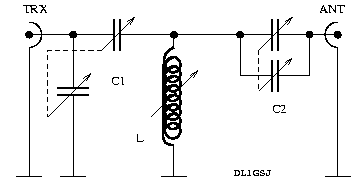
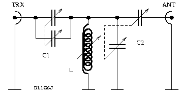
Next try, the SPC transmatch
Circuit description
For theoretical background I would like to point the reader to the common standart literature as the famous RF textbook of Meincke and Gundlach, or comparable other readings. The first approach was thought as an experiment to understand the so called ultimate transmatch (UT, first proposed by Lew McCoy). In principle I would recommend this design, also driven by my practical experience. It delivers good matching with moderate bandwidths. Besides that this design might have a slightly higher loss.Apart from what I have written in the first version of this text, all the parts were fine to build a UT-ATU, but the rotary switch, and my attention at this time, fooled me. Thinking I got a 1x12 switch, I soldered the wires fitting this type. A few days later, reading a catalogue, it was clear, that the built in think is a 2x6 type. An additional switch cured the "problem". So, the finally completed ATU now is an UT.
Advantages: very smooth tuning even at the more critical frequencies like 29.690MHz, our local (Hamburg, Germany) repeater. QRO in this design seems not to be harmful at all, 120W RF on all available bands (40m to 10m) were matched to a 2m wire as well as to a 10m wire w/o sparkling ATU ;-)
As a comparison, I chose the series-parallel capacitance transmatch (SPC), for the reason that it took me just two leads reconfigured to convert on to another. Formerly I also planned to test the standart transmatch, but the overwhelming wish to get on air forced me to stay at the simple - to - obtain - by - the - most - simple - modification - design (smiley!). Disadvantages in this design (agn, have a glance to the textbooks) are the extreme narrow bandwidths and the low QRO ability (high Q).
What to chose if money plays no role? Certainly I would go for the UT, with two two-gang vernier capacitors at 1nF max (in both sections) and a roller inductor... if... but... it's all built from the junk-box.
Parts descriptions
The capacitors are the simple part. I just found them on the bottom of my junk box. They look like they were intended to go into AM broadcast receivers. In either design one has both sections wired in parallel. The inductor, the tricky thing in matching units with variable inductance. For the body I found an old pill container with a diameter of 4cm. The coil is then wound on this with 60 windings of 1mm enameled copper wire. The first 36 windings tight together, the rest with increasing wire to wire distances to the upper (hot) end of the coil. Tabbings are located at the windings 19, 28, 37, 42, 47, 50, 53, 55, 57, 58 and 59 for use with a 12 positions rotary switch shortening to ground, as I thought... In reality it's a 2x6 with an additional switch.SWR indicator
My good friend Rico (DF2CK) had the heart to donate a PCB reflectometer to me. To make one yourself, have a look at Harry's (SM0VPO) Homebrew Page. Can't remember the way Harry did the rest, I added a 47k potentiometer for sensitivity adjustment, and a 4k7 suppression resistor to the forward meter, for reasonable reading during the tuning process. The meter itself is a standart stereo VU-meter, found in obsolete tape recorders (other superb parts could be found there likewise). Usage: Highest sensitivity and lowest reasonable RF power to start with. During the tuning you certainly will increase the RF power the closer you are to good matching. With CW, your favoured mode ;-), you then automaticaly will have the correct sensitivity setting during QSOs. For SSB contacts, you should keep in mind to reduce the sensitivity close to zero after tuning. The clicking meters will remember you to do so elsewise. Weak nerves would make you think of a sparkling capacitor, hi!Tuning procedure
Yes, I know, that's common knowledge... but... we have two designs in this report. My experience was that the both designs have a contrary behaviour. Tuning with the UT: Fiddle during RX with all the buttons to get the loudest noise. You're allready close! Next is done with a little RF applied, power depending on the band, little fine tuning, done! QSO! Tuning mainly was done during RX. On the other hand I experienced that the RX maximum must not be the minimum in SWR.Tuning with the SPC transmatch: More difficult, because of the narrow bandwidths. Set your transmitter to a few tens of milliwatts to find a C-L-C combination where the reflected power is halfways acceptable. Now the game begins! By slightly in/de-creasing certain capacities and inductivities find a good match. You will notice, it's much more complicated to find a good match, as the SPC transmatch with the given parts will provide exactly one for a specific aerial<->QRG combination.
Experiences
Clearly the SPC transmatch easily is able to match a 2m wire to 3.5Mhz w/o any problem, but, whatever band you're QRV on, watch the reflected power... Using the SPC transmatch, you will have to retune every tens of kHz. The UT give, as mentioned above, broader bandwidths. With both designs it now is possible to match a 2m wire to all bands (even 160m, although this makes no sense at all). It was easy to confirm the statements given in the literature about the behaviour of the presented matching networks. So, before you start soldering, think about what kind of aerial you want to match, and have a closer look to the textbooks. The opinion given there is that the UT can better handle inductive loads while the SPC transmatch is performing smoother on capacitive loads.Photographs
The inductor. I know, does not look extremely professional...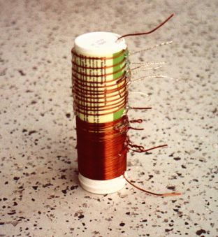
Box, partially assembled. The capacitors are glued to PVC insulators (using hotglue). Also the pill container inductor is glued to the box. On the left side, you can see the reflectometer PCB.
Box, completed. The knobs for the capacitors nowadays are replaced by larger ones, depending on the settings your hand has a strong influence to the capacities.
Simple 70cm GP-antenna
70cm Ground Plane Antenna
Materials used
- about 90cm of 1mm silver steel rod
- one luster terminal with at least two
- 50Ohms coax cable
- glass fibre mast
lead guides beeing able to carry 2mm leads
Construction & Design
Sketches or drawings are IMHO not necessesary because of the extreme simplicity of the "design". Cut 19cm off the rod, and bend 2cm at one end by an angle of 90°. This will be the radiator, 17cm straight up in the air. It will directly go in one whole of the luster terminal. Watch out, that the terminal´s skrews are pointing downwards, elsewhise you will later have problems with water and corrosion. The radials are made of two rods with a length of 34cm. Stick both through the other whole of the luster terminal, centered. You might now bend each rod to an angle of 90°, with the luster terminal in it´s centre. To give it the correct feed-point impedance the radials should be twisted slighly downwards.Connect the coax cable to your little aerial, using again the abilities of the terminal. BTW, I used RG174 (lossy!) for the last meter, to reduce the weight.
In the middle of modern luster terminals there are wholes, to mount the terminal wherever it should go to. This whole (3mm) is perfect to stick the mast through. At the very top mine has a diameter of 2.8mm. This makes the ground plane to rest only 12cm below the top.
Alignment
In principle exactly the same way as for any other antenna, you have built up to know. Find it´s resonance, and cut off as much as needed to obtain the desired resonance frequency. The SWR can be improved by variing the downward angles of the radials.Experience
I am happy! Whenever the reflection I have to use with my indoor HB9CV-antenna does not provide nice signals, I can errect the glass-fibre mast with the ground plane, and establish a stable link to my local digipeater (running the transceiver´s lowest power setting). Besides that I could hear a lot more phone repeaters than before. The only pitty is, that I do only posses one such mast... so, no shortwave during packet, or vica versa :-(Photographs
Taken at 31.12.2000, the last day of the second millenium... Various angles and views...

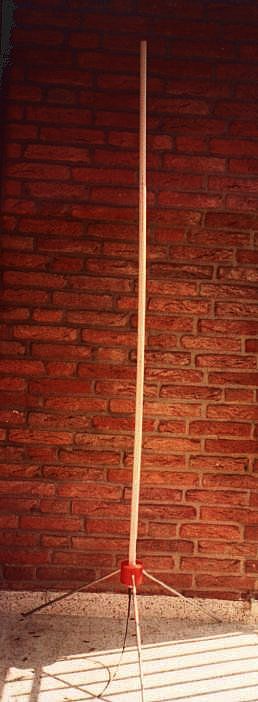
2m J-Pole Antenna
Simple J-Pole for the 2m band
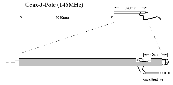
To adjust the SWR you will have to "play" with the 40mm distance between the coax feed and the braid -- inner conductor connection. I could obtain a SWR of 1:1 at 145MHz. All together in my favourite material, PE tubing, with a simple tripod this makes my 2m standby aerial.
Photograph taken on my balkony.
Subscribe to:
Comments (Atom)