Sunday, September 5, 2010

QRSS Averaging - Redundancy

With the help of Alessandro IW3SGT, I was able to collect some interesting data. Alessandro set his transmission so that his ident is sent out twice in a 10min period. Timing was perfect!
Towards the end of the session, strong fading dominated the game, and this is what this entry is about.

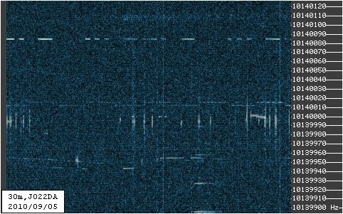
The last 30min of the opening look exactly like this

1800z - 1810z
1810z - 1820z
1820z - 1830z

The above spectra never show "SGT" completed. Have a look at the average of those spectra:


Here we go, thanks to the ident being TXed twice in the course of 10min, it is easy to figure out the ident from the averaged spectra.

BTW, adding the frame from just before the above mentioned 30min, result is really obvious...

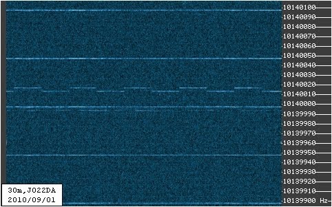
1750z - 1800z
40m average
I am not sure, I remember to have observed a QSB frequency having a period of about 10min, that was on 600m, trying to decode G3ZJO's WSPR. Maybe a 10min averaging is not such a good idea after all, and 5min should be chosen.

Saturday, September 4, 2010

QRSS Averaging vs Plasma TV - 2nd Test

Short update on averaging fighting a plasma TV.

I selected the best and the worst of the 10 frames used for averaging. It seems that every plasma TV has got its own finger-print...

Let's have a look:

best frame

worst frame

average of 10 frames
... using the (old) dark frame
... dark frame and cut "low" pixels
This shows, as long as the local noise is regular enough, one can either simply ignore it, or fight it with simple measures. I think, I could do better on the dark frame story, however, I still lack pure TV signal to create my "plasma frame".


UPDATE
6 frames stacked (no dark frame), positive QRSS identification of "SGT" despite the plasma TV... more to learn. I should make my dark frame soon.
positive identification of SGT

Friday, September 3, 2010

Magic super-VXO Frequency?

Years ago, I ebayed a Heathkit HW-8 direct conversion CW-transceiver. It was not in the best shape, but it did not cost the world either. Now, for good measures, finally I want to put some life in it again. So, lets look at the schematics first...
Ahh, mhhhh, aha..... four bands, four crystals and a 250kHz wide VFO.
Lets have a look at the combination for 80m:
The converter-crystal is mentioned to be 12.395MHz. That would determine the VFO oscillating at 8.895MHz at its maximum frequency.

Hmm, 8.645MHz to 8.895MHz, that rings a bell! Yes, you guessed it, there is a widely available standard crystal at 8.86724MHz, resulting a very interesting operating frequency at about 3.528MHz... Interesting, a super-VXO at 8.867MHz, will get us 28kHz off from the lower edges of the four bands.

Now lets see how well a 8.867 super-VXO will do with other standard crystals...
  • 8.867 - 9.000 = (-) 0.133
  • 8.867 - 7.000 = 1.867
  • 8.867 - 12.406 = (-) 3.539
  • 8.867 - 1.843 = 7.024
  • 8.867 + 5.185 = 14.052
  • 8.867 + 9.216 = 18.083
 You're missing 30m? OK, here's your 30m, it's a tricky one however, in particular for filtering!
  • 8.867 + (5.000/4) = 8.867 + 1.25 = 10.117
 Or with a not so common 38.0MHz oscillator:
  • 8.867 - (38.000/2) = 8.867 - 19.000 = (-) 10.133

I leave it to the reader to find more, in particular for the bands 15m and higher...

Thursday, September 2, 2010

QRSS Averaging vs Plasma TV

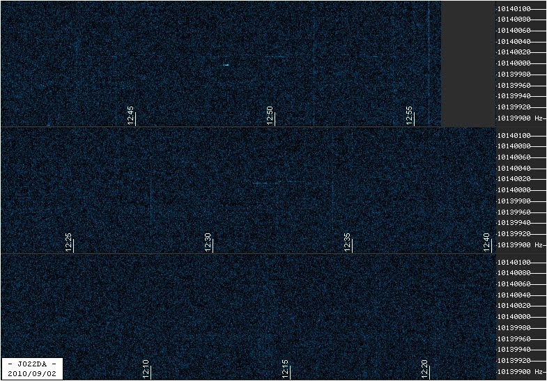
Well, what about those, would you think that any reasonable signal identification can be derived from this? "Ja hoor!"


Raw Data

Feel free to download the images and try for yourself!


Averaged Spectrum

And we can identify Paolo once again ;-)


Dark Frame Technique vs Plasma TV

A plasma TV creates some more or less static lines, like hot pixels in a long exposure CCD camera. The dark frame technique subtracts the "ideal" hot pixel map, or TV lines, in our case. A dark frame is created the same way as the averaged spectum. In the case of a CCD camera, one simply puts the lid on the objective lens. For TV, life is more complicated. To create a dark frame, I selected spectra were the TV lines were essentially the only signals present. Maybe, in a second step, one may want to try to capture spectra of the particular noise source with an insensitive antenna close by...
That would be my dark frame for tonight (5 selected spectra averaged):


With dark fram "opacity" set to 30%, that's what the little averaging program comes up with:


DF opacity set to 100%, pixel values of less than 160 are set to 0.


Dark Frame Technique vs OTHR

Yep, this technique is suitable for getting rid of radar stuff too. To me, it seems more to help aesthetics than anything else... but... you never know.
Last night, nice radar spectra were recorded. A couple of those resulted in the following radar "dark frame":


Earlier today, that was recorded... (averaged)


Averaged using the dark frame:


Conclusion

Those are my first steps using my experience in imaging gather in long-exposure webcam deep sky photography. I am in a very early stage using said techniques in QRSS imaging. My impression is,
imaging techniques used in astrophotography can help QRSS. Those techniques can even help fighting local QRM. A lot more learning is required... I remember my learning curve in astro-stuff... my first astro-images totally sucked!

Daytime Averaging

Unfortunately, the night did not really reveal any good condx. However, during daytime, very poor condx allowed to see some Southern European signals.

During the time span in question, the regular grabber took the following spectra


In the time between 10:30 and 13:00 UTC, 15 10min spectra were taken. Successive 5 of those spectra were average into 3 intermediate results, which were averaged again. Remember the demo-version of the stacking software allows for max. 10 images to be treated.


Averaging Result


Metallic Effect (irfanview)


Paolo's FSK signal nicely spreads over the full 10min span. Due to fading, the signal never made it into JO22 for any continuous 10min, as the 15 "frames" show.

The SNR could be further improved by selecting the best spectra, i.e. with at least some signal. I went for the "blind" method (using all frames) an automatic grabber would perform.

If interested in the raw spectra (frames), drop a comment, I will make a zip-file available for download.

QRSS Image Averaging

First test on 10min QRSS spectra averaging using http://tawbaware.com/imgstack.htm
Thanks to NH7SR, it seem somewhat obvious how to record timed spectra. With good stability and timing assume, image registration seems not to be required. Hence, simple stacking or averaging would be a promising start. Here's some first stuff, not refined yet... a somewhat early pre-alpha stage.


Raw Data

The following 6 images are raw spectra, as recorded and used for the averaging.

Raw
Raw
Raw

Raw

Raw

Raw


Averaging Result

Average


Conclusion

The settings are pretty much same used for the online grabber. For an averaging grabber, more noise, i.e. contrast & brightness, could be tolerated. Data acquisition with more aggressive settings is presently ongoing.
I believe, the first hour, compressed into 10 minutes show a promising start and some potential when the learning curve is surpassed.


Update

Some more spectra are in, as promised, more aggressively set. This is what those look like.

Raw
Raw
Raw
Raw
Average

Tuesday, August 31, 2010

MF/LF Dual Band SDR

Just an idea, what about a 2.000MHz local oscillator. For regular SDR purposes, this will and up at 500kHz centre frequency. Ok... not that surprising.
What about taking this 500kHz signal and use it as LO for another SDR setup. Well, that would provide as with a centre frequency of 125kHz.

Assuming a regular 48kH sampling, two interesting frequencies are in reach:
  • MF: 476-524kHz
  • LF: 101-149kHz

Wednesday, August 18, 2010

H-Probe (the Aerial Formerly Known As Shielded Loop)

Short update, not only the name changed, some more happend.
Parts are collected, the TL592 based amplifier should be done in minutes.
The shielded loop is past now, I will reorganise the inside of the tuning-box. The toroid is removed, coupling will be done at the high impedance region of the loop, i.e. at the tuning capacitor.

Oh, should you wonder about the new name, this contraption is near to entirely screened, any E-field should therefore essentially be excluded from detection. A magnetic field, or H-field, will induce a current in the loop. This current will peak at the resonance frequency, creating a high impedance RF signal across the tuning capacitor. The aerial therefore probes the H-field, hence the new name.

Tuesday, August 17, 2010

Multiband QRP TRX

Just an idea, which pop up when I replied to G4CWX and had a chat with PA9QV. The question was, what to use as a low power travel CW setup.
And this is the idea: a couple of RockMites in a box.
All transceivers could share the connector, i.e. antenna socket, control button, key. Band select, in my plan, would be a rotary switch powering up an individual transceiver PCB.
As said, just an idea....
And... I still got the RockMite kits for 20, 30 and 40m waiting for solder... the 80m version could be brought from QRSS to QRP... the 4-band-QRP-TRX would be completed.

Shielded Loop (some photographs)

No new development yet. Here are some photographs to help the imagination. The loops will be provided with some amplifiers soon-ish.

There seems to be a rule of thumb for the dimensions:
Loop Diameters [cm] = Wavelength [m]

(e.g. 30cm loop diameter for a 10MHz loop)  :-))

For more information on materials and dimensions, please use the label "shielded" down below.


The loops for 30m and 40m.
The gap in the shield, opposite the capacitor.
The capacitor and coupling "box".